
Kia Stinger CK: Wide Sunroof / Mechanism Rail
Components and components location
| Components Location |
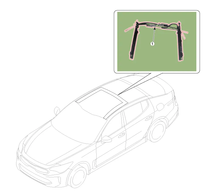
| 1. Mechanism Rail |
Repair procedures
| Replacement |
Put on gloves to protect your hands. |

|

| 1. |
Remove the roof trim. (Refer to Roof Trim - "Roof Trim Assembly") |
| 2. |
Tilt the moving glass by using the wide sunroof switch.
|
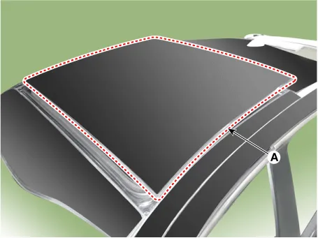
| 3. |
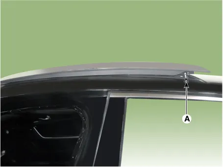
Remove the both sides mechanism cover (A).
|
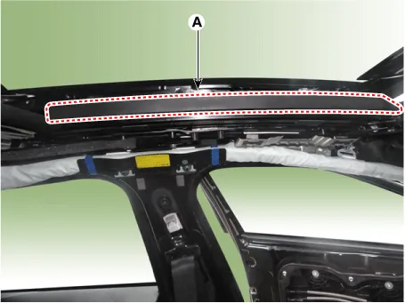
| 4. |
Loosen the mounting screws (A) on both sides.
|
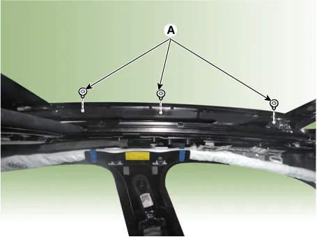
| 5. |
Carefully lift up the moving glass (A) and then remove it.
|
| 6. |
Open the roller blind by pressing sunroof switch.
|
| 7. |
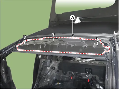
Remove the roller cover (A) after loosening the mounting screw.
|
| 8. |
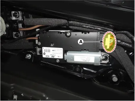
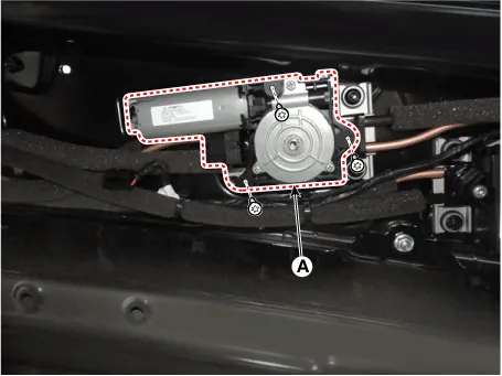
Disconnect the roller blind motor and the moving glass motor connector. [moving glass motor]
[roller blind motor]
|

| 9. |
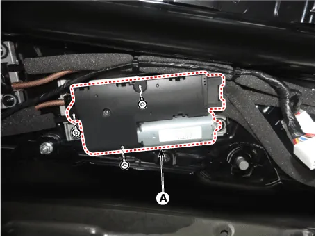
Remove the roller blind motor and the moving glass motor after loosening the mounting screws. [moving glass motor]
[roller blind motor]
|
| 10. |
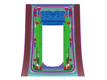
Loosen the mechanism assembly mounting screws.
|
| 11. |
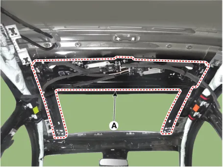
Remove the mechanism rail assembly(A).
|
| 12. |
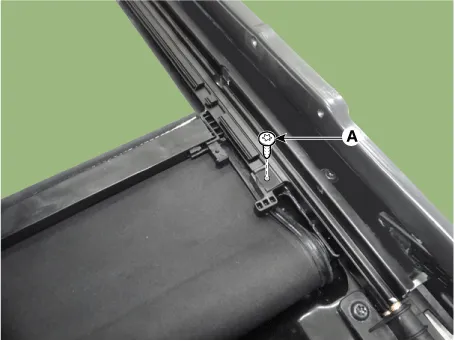
Loosen the roller blind lead mounting screw (A).
|
| 13. |
Remove the roller blind lead (A) from the mechanism rail.
|
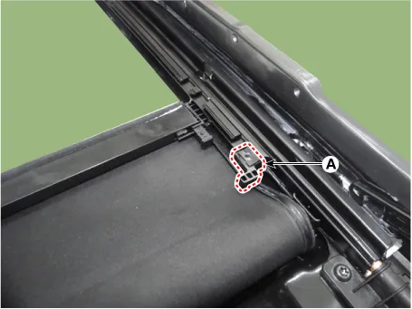
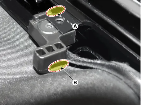
| 14. |
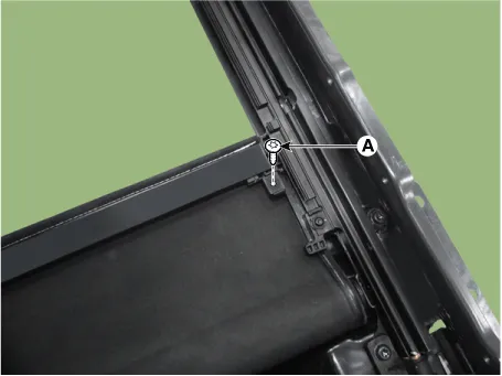
Loosen the roller blind shoe clip mounting screw (A).
|
| 15. |
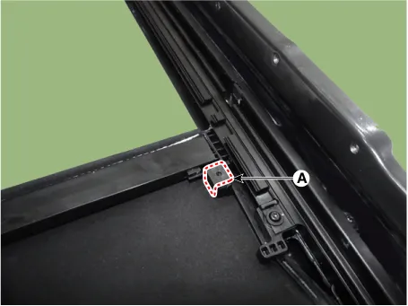
Remove the roller blind shoe clip (A).
|
| 16. |
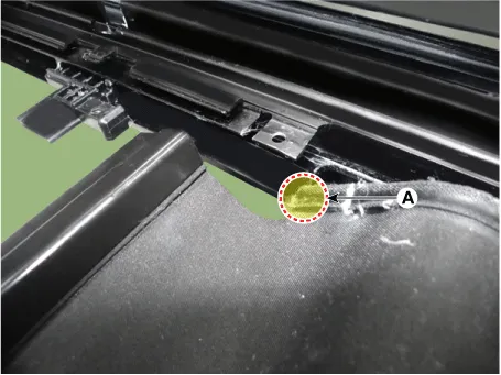
Remove roller blind bar (B) by pressing locking pin (A) with using flat-tip screwdriver.
|

| 17. |
Loosen the drive unit mounting nuts.
|

| 18. |
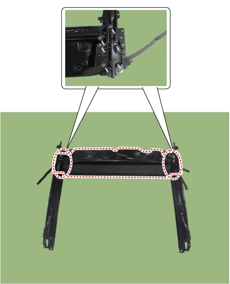
Loosen the roller blind mounting screws.
|
| 19. |
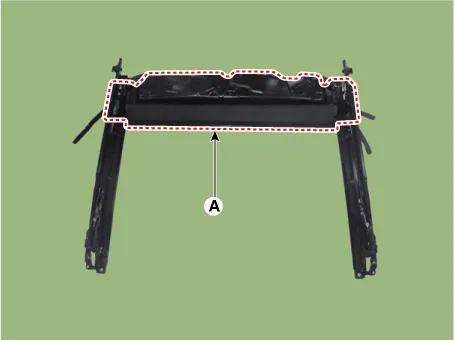
Remove the roller blind(A) from the mechanism rail.
|
| 20. |
Installing order is inverse order of removing.
|
| Adjustment |
Initialize mechanism rail.
Follow the instruction down below to initialize both side mechanism rail when the mechanism rail and mechanism assembly are removed or installed.
| 1. |
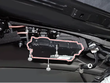
Separate the glass motor(A) from drive gear after loosening the installed screws.
|
| 2. |
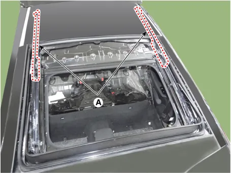
Open both mechanism assembly (A) as much as possible.
|
| 3. |
Open the glass motor as maximum by pressing sunroof switch after IG is ON. |
| 4. |
Install the moving glass motor on drive gear. |


Other information:
Kia Stinger (CK) 2018-2023 Service Manual: Side Airbag (SAB) Module
Description and operation Description Installed inside the front seat, the side airbags (SAB) protect the driver and front passenger from danger in the event of a side crash. The SRSCM determines deployment of side airbag based on Side Impact Sensor (SIS) signal. Never attempt to measure the circuit resistance of the airbag module (squib) even if you are using the specified tester.Repair procedures Smart Key Smart Key Code Saving 1. Connect the DLC cable of KDS to the data link connector (16 pins) in driver side crash pad lower panel, turn the power on KDS. 2. Select the vehicle model and then do "Smart key code saving". 3.Categories
- Manuals Home
- Kia Stinger Owners Manual
- Kia Stinger Service Manual
- New on site
- Most important about car
