Kia Stinger CK: Power Tailgate System / Power Tailgate Module
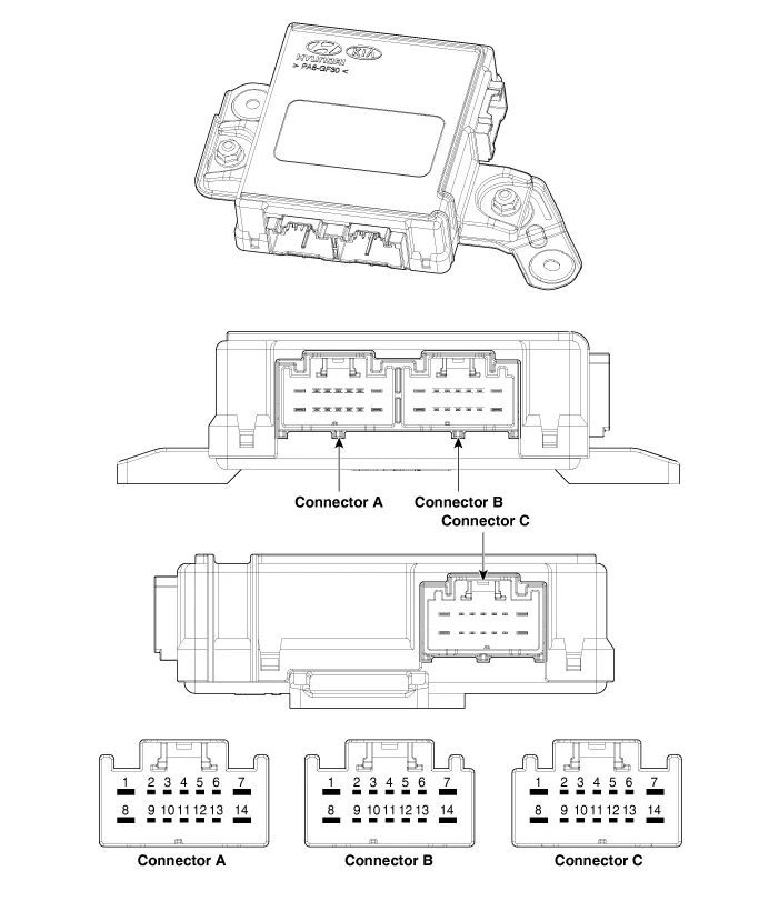
Components and components location
| Components |
|
No. |
Connector A |
Connector B |
Connector C |
|
1 |
Power supply |
Cinching motor (+) |
Spindle motor (RH)_Close (-) |
|
2 |
Illumination (Tailgate inner switch) |
Tailgate full open switch |
Hall sensor (RH)_Power |
|
3 |
- |
Tailgate full lock switch |
Spindle (LH) shild_Ground |
|
4 |
B-CAN (High) |
Tailgate half lock switch |
Hall sensor (RH)_Ground |
|
5 |
B-CAN (Low) |
Home position switch_Ground |
Spindle (RH) shild_Ground |
|
6 |
Buzzer |
Tailgate latch switch _Ground |
Hall sensor (LH)_Power |
|
7 |
- |
System ground |
Spindle motor (LH)_Close (+) |
|
8 |
Tailgate motor |
Cinching motor (-) |
Spindle motor (RH)_Close (+) |
|
9 |
- |
Tailgate open/close switch |
Hall sensor 1 (RH) |
|
10 |
Gear 'N' Position |
Tailgate inner switch |
Hall sensor 2 (RH) |
|
11 |
- |
Home position switch |
Hall sensor (LH)_Ground |
|
12 |
Antipinch strip (LH)_Power |
Antipinch strip (LH)_Ground |
Hall sensor 1 (LH) |
|
13 |
Antipinch strip (RH)_Power |
Antipinch strip (RH)_Ground |
Hall sensor 2 (LH) |
|
14 |
- |
Power ground |
Spindle motor (LH)_Close (-) |
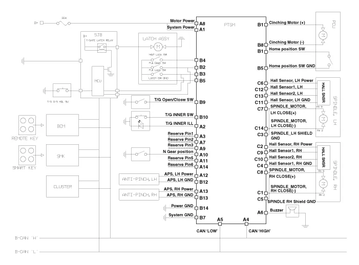
Schematic diagrams
| Circuit Diagram |
Repair procedures
| Removal |
|

| 1. |
Disconnect the negative (-) battery terminal. |
| 2. |
Remove the luggage side trim [LH]. (Refer to Body - "Luggage Side Trim") |
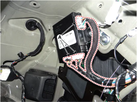
| 3. |
Disconnect the power tailgate module connectors (A).
|
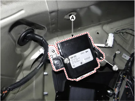
| 4. |
Remove the power tailgate module (A) after loosening the mounting nuts.
|
| Installation |
| 1. |
Install the power tailgate module. |
| 2. |
Connect the power tailgate module connectors. |
| 3. |
Install the luggage side trim [LH]. |
| 4. |
Connect the negative (-) battery terminal. |
| Inspection |
Inspection of the Power Tailgate Module
Refer to Power Tailgate System - "Troubleshooting"


Other information:
Kia Stinger (CK) 2018-2023 Service Manual: Blind-Spot Collision Warning (BCW) Switch
Schematic diagrams Circuit Diagram Repair procedures Removal 1. Disconnect the negative (-) battery terminal. 2. Remove the crash pad lower panel. (Refer to Body - "Crash Pad Lower Panel") 3. Remove the crash pad garnish [LH] (A) after loosening the mounting screw.Kia Stinger (CK) 2018-2023 Service Manual: Active hood lift system
Description and operation Description The system reduces injury of pedestrians by lifting the hood when a accident occurs between the pedestrian and vehicle. It may prevent a secondary impact between the pedestrian's head and engine components. Components and components location Components Location 1.Categories
- Manuals Home
- Kia Stinger Owners Manual
- Kia Stinger Service Manual
- New on site
- Most important about car
