Kia Stinger CK: Rear Suspension System / Rear Cross Member
Repair procedures
| Removal |
| 1. |
Remove wheel nuts, wheel and tire (A) from hub.
|


| 2. |
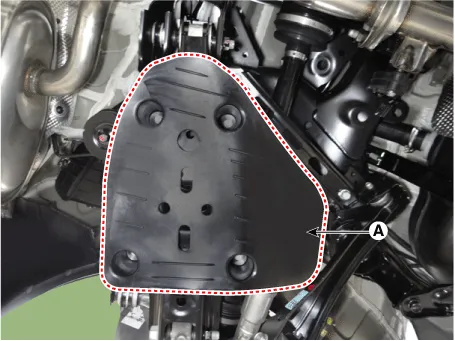
Remove the rear lower arm cover (A).
|
| 3. |
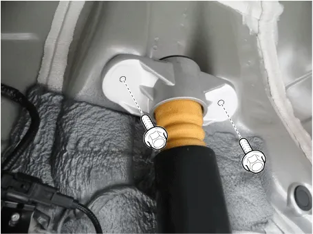
Loosen the rear shock absorber upper bolts and the remove the rear shock absorber.
|
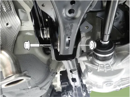
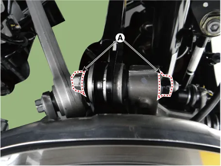
| 4. |
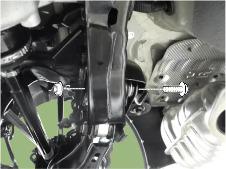
Loosen the bolt (A) and then separate the rear assist arm from the rear axle.
|
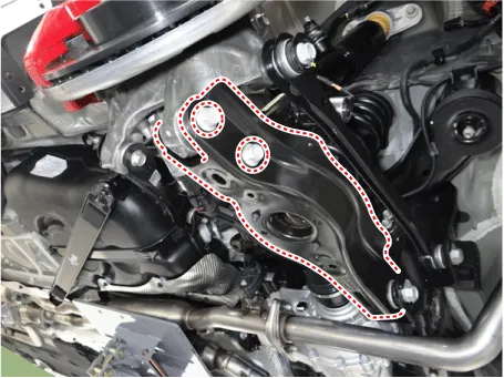
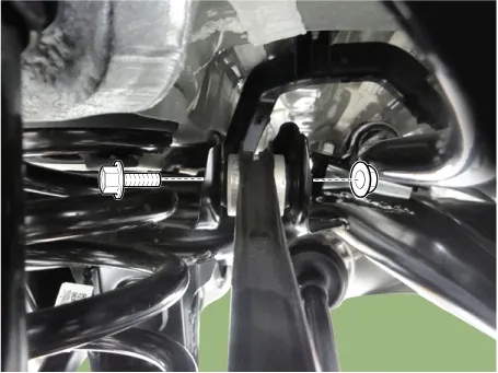
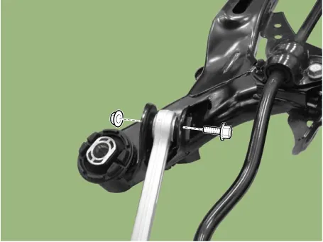
| 5. |
Loosen the bolt & nut and then remove the rear assist arm from the rear cross member.
|
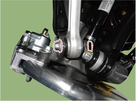
| 6. |
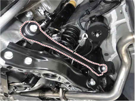
Loosen the rear lower arm bolt & nut and then separate the lower arm from the rear axle.
|
| 7. |
Loosen the bolt & nut and then remove the rear lower arm.
|
| 8. |
Loosen the trailing arm bolt & nut and then remove the trailing arm.
|
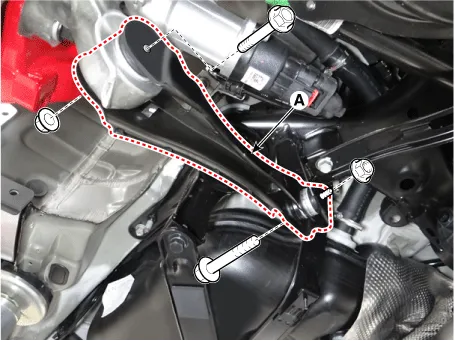
| 9. |
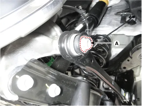
Loosen the rear upper arm rear bolt & nut (A) and then separate the rear upper arm rear.
|
| 10. |
Loosen the rear upper arm rear bolt and then remove the rear upper arm rear.
|
| 11. |
Loosen the bolt & nut and then remove the rear upper arm front from the rear axle.
|
| 12. |
Remove the propeller shaft. (Refer to Driveshaft and axle - "Propeller shaft") |
| 13. |
Remove the rear muffler. D 2.2 R VGT (Refer to Engine Mechanical System - "Muffler") G 2.0 T-GDI THETA II (Refer to Engine Mechanical System - "Muffler") G 3.3 T-GDI LAMBDA II (Refer to Engine Mechanical System - "Muffler") |
| 14. |
Remove the rear driveshaft. (Refer to Driveshaft and axle - "Rear drive shaft") |
| 15. |
Remove the rear axle. (Refer to Driveshaft and axle - "Rear hub / Carrier") |
| 16. |
Remove the rear differential. (Refer to Driveshaft and axle - "Rear Differential Carrier") |
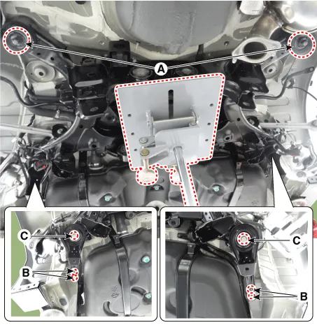
| 17. |
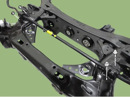
Loosen the rear cross member nuts & bolts and then remove the rear cross member.
|
| 18. |
Loosen the stabilizer bar nuts & bolts and then remove the stabilizer bar.
|
| 19. |
Loosen the rear upper arm front nut & bolt and then remove the rear upper arm front from the rear cross member.
|
| 20. |
Remove the damper from the rear cross member.
|

| 21. |
Install in the reverse order of removal.
|
| 22. |
Check the alignment. (Refer to Suspension System - "Alignment") |


Other information:
Kia Stinger (CK) 2018-2023 Service Manual: To keep locks from freezing
To keep the locks from freezing, squirt an approved de-icer fluid or glycerine into the key opening. If a lock is covered with ice, squirt it with an approved de-icing fluid to remove the ice. If the lock is frozen internally, you may be able to thaw it out by using a heated key. Handle the heated key with care to avoid injury. Use approved window washer anti-freeze in system To keep the water in the window washer system from freezing, add an approved window washer anti-freeze solution in accordance with instructions on the container.Kia Stinger (CK) 2018-2023 Service Manual: Rear Transverse Trim
Components and components location Component Location 1. Rear pillar trim Repair procedures Replacement Put on gloves to protect your hands. • Use a plastic panel removal tool to remove interior trim pieces without marring the surface.Categories
- Manuals Home
- Kia Stinger Owners Manual
- Kia Stinger Service Manual
- New on site
- Most important about car
