Kia Stinger CK: Rear Suspension System / Rear Stabilizer Bar
Repair procedures
| Removal |
| 1. |
Remove wheel nuts, wheel and tire (A) from hub.
|


| 2. |
Remove the brake caliper. (Refer to Brake system - "Rear disc brake") |
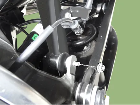
| 3. |
Loosen the stabilizer link nut and then separate the rear axle.
|
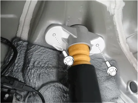
| 4. |
Loosen the rear shock absorber upper bolts and the remove the rear shock absorber.
|
| 5. |
Remove the propeller shaft. (Refer to Driveshaft and axle - "Propeller shaft") |
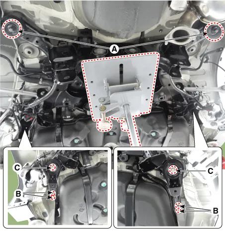
| 6. |
Remove the rear muffler. D 2.2 R VGT (Refer to Engine Mechanical System - "Muffler") G 2.0 T-GDI THETA II (Refer to Engine Mechanical System - "Muffler") G 3.3 T-GDI LAMBDA II (Refer to Engine Mechanical System - "Muffler") |
| 7. |
Loosen the rear cross member nuts & bolts and then remove the rear cross member.
|
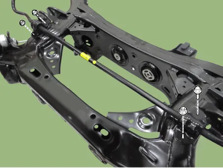
| 8. |
Loosen the stabilizer bar nuts & bolts and then remove the stabilizer bar.
|
| 9. |
Install in the reverse order of removal. |
| 10. |
Check the alignment. (Refer to Suspension System - "Alignment") |
| Inspection |
| 1. |
Check the rear stabilizer bar for deformation. |
| 2. |
Check the rear stabilizer link ball joint for damage. |


Other information:
Kia Stinger (CK) 2018-2023 Service Manual: Tire (pressure & tread wear)
Repair procedures Inspection 1. Check the tire pressure. 17(inch) : 245 + 7.0 kPa (36 + 1 psi) 18(inch) : 245 + 7.0 kPa (36 + 1 psi) 19(inch) : 245 + 7.0 kPa (36 + 1 psi) Tire Rotation Checking For Pull And Wander If the steering pulls to one side, rotate the tires according to the following wheel rotation procedure.Kia Stinger (CK) 2018-2023 Service Manual: Tire terminology and definitions
Air Pressure: The amount of air inside the tire pressing outward on the tire. Air pressure is expressed in kilopascal (kPa) or pounds per square inch (psi). Accessory Weight: This means the combined weight of optional accessories. Some examples of optional accessories are, automatic transaxle, power seats, and air conditioning. Aspect Ratio: The relationship of a tire's height to its width.Categories
- Manuals Home
- Kia Stinger Owners Manual
- Kia Stinger Service Manual
- New on site
- Most important about car
