Kia Stinger CK: Driveshaft and axle / Rear Driveshaft Assembly
Repair procedures
| Removal |
| 1. |
Remove wheel nuts, wheel and tire (A) from hub.
|


| 2. |
Remove the rear brake caliper. (Refer to Brake System - "Rear Disc Brake") |
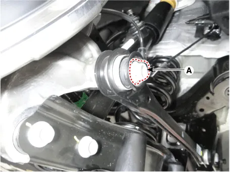
| 3. |
Remove the split pin (A) from the rear hub and loosen the hub nut (B).
|

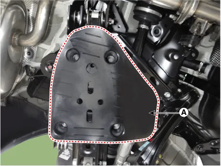
| 4. |
Remove the rear lower arm cover (A).
|
| 5. |
Remove the wheel speed sensor.
|

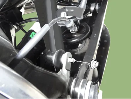
| 6. |
Loosen the stabilizer link nut and then separate the rear axle.
|
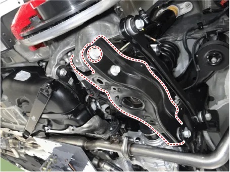
| 7. |
Loosen the rear lower arm bolt & nut and then separate the rear lower arm from the rear axle.
|
| 8. |
Loosen the nut & bolt and then separate the trailing arm from the rear axle.
|
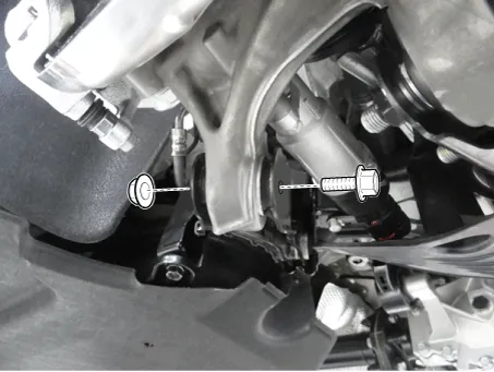
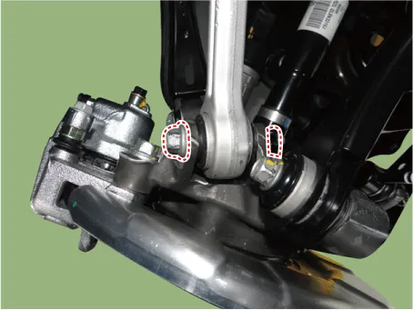
| 9. |
Loosen the bolt (A) and then separate the rear assist arm from the rear axle.
|
| 10. |
Loosen the bolt & nut and then remove the rear upper arm front from the rear axle.
|
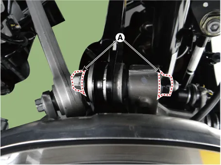
| 11. |
Loosen the rear upper arm rear bolt & nut (A) and then separate the rear upper arm rear.
|
| 12. |
Separate the rear drive shaft from the knuckle.
|

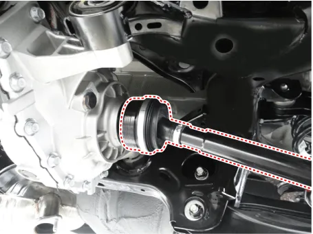
| 13. |
Using pry bar, remove the rear drive shaft from the rear differential.
|
| 14. |
Install in the reverse order of removal. |


Other information:
Repair procedures Removal 1. Remove the engine room front under cover. (Refer to Engine and Transmission Assembly - "Engine Room Under Cover") 2. For release the tension, turn the drive belt tensioner (A) counterclockwise then remove the drive belt (B). 3.Components and components location Components 1. Rear seat cushion pad 2. Rear seat cushion heater 3. Rear seat cushion covering 4. Rear seat back covering 5. Rear seat back pad 6. Rear seat back frame back panel 7. Rear seat back folding knob [LH] 8. Rear seat back folding knob cover [LH] 9.Categories
- Manuals Home
- Kia Stinger Owners Manual
- Kia Stinger Service Manual
- New on site
- Most important about car
