Kia Stinger CK: SRSCM / Side Impact Sensor (SIS)
Description and operation
| Description |
| • |
Side Impact Sensor (SIS) system consists of two Pressure Side Impact Sensor (P-SIS) installed at each center of the front door module (LH and RH), two SIS installed at each center pillar nearby (LH and RH) and two rear SIS installed in the rear pillar (LH and RH). |
| • |
Pressure Side Impact Sensor is also called P-SIS because it detects pressure from collision at its mounting location. |
| • |
Side Impact Sensor is also called A-SIS because it detects acceleration. |
| • |
SRSCM decides deployment of the airbag and the time of deployment through the collision signal of the SIS when the collision occurred. |
Components and components location
| Components |
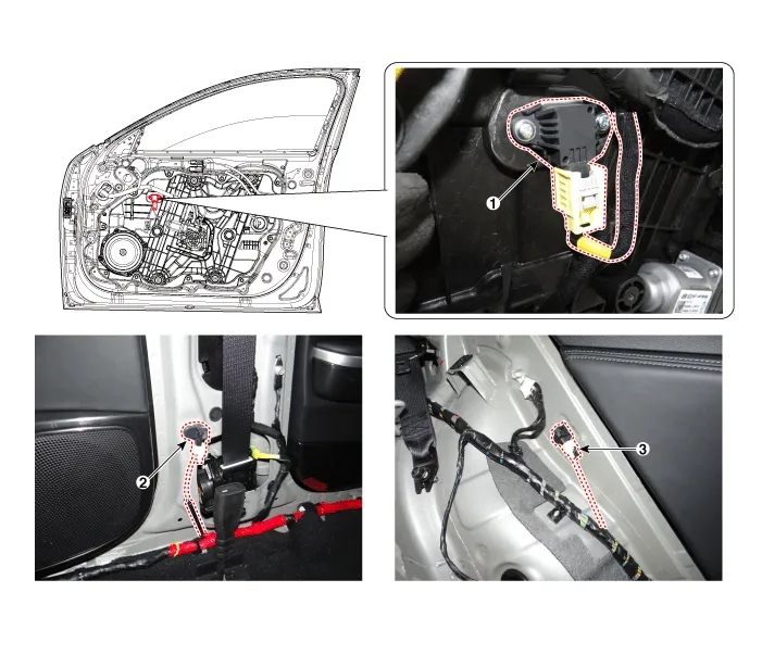
| 1. Front Pressure Side Impact
Sensor (P-SIS) 2. Front Gravity Side Impact Sensor (G-SIS) |
3. Rear side Impact Sensor (R-SIS)
|
Repair procedures
| Removal |
Front Pressure Side Impact Sensor (P-SIS)
| 1. |
Disconnect the negative battery terminal, and wait for at least thirty seconds before beginning to work. |
| 2. |
Remove the front door trim. (Refer to Body (Interior and Exterior) - "Front Door Trim") |
| 3. |
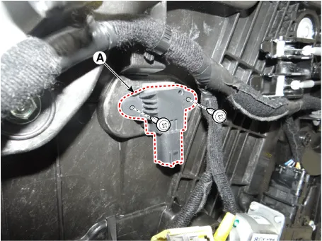
Remove the pressure side impact sensor (A).
|

| 4. |
Loosen the side pressure sensor mounting screw, and remove the sensor (A).
|
Front Gravity Side Impact Sensor (G-SIS)
| 1. |
Disconnect the negative battery terminal, and wait for at least thirty seconds before beginning to work. |
| 2. |
Remove the door scuff trim. (Refer to Body (Interior and Exterior) - "Door Scuff Trim") |
| 3. |
Remove the center pillar trim. (Refer to Body (Interior and Exterior) - "Center Pillar Trim") |
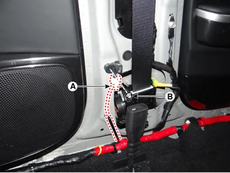
| 4. |
After disconnecting the side impact sensor connector (A) and loosening the bolt (B), remove the sensor.
|
Rear Side Impact Sensor (R-SIS)
| 1. |
Disconnect the negative battery terminal, and wait for at least thirty seconds before beginning to work. |
| 2. |
Remove the rear seat assembly. (Refer to Body (Interior and Exterior) - "Rear Seat Assembly") |
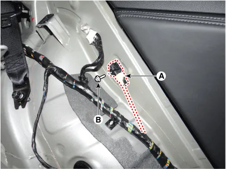
| 3. |
Remove the rear side impact sensor connect (A). |
| 4. |
Loosen the rear side impact sensor nut (B), and remove the sensor.
|
| Installation |
Front Pressure Side Impact Sensor (P-SIS)
| 1. |
Disconnect the negative battery terminal, and wait for at least thirty seconds before beginning to work. |
| 2. |
Install in the reverse order of removal. |
| 3. |
After installing the pressure side impact sensor, confirm proper system operation: • Switch "ON" the ignition. The SRS indicator light should turn on for about six seconds and then off.
|

Front Gravity Side Impact Sensor (G-SIS)
| 1. |
Disconnect the negative battery terminal, and wait for at least thirty seconds before beginning to work. |
| 2. |
Install in the reverse order of removal. |
| 3. |
After installing the side impact sensor, confirm proper system operation: • Switch "ON" the ignition. The SRS indicator light should turn on for about six seconds and then off. |
Rear Side Impact Sensor (R-SIS)
| 1. |
Disconnect the negative battery terminal, and wait for at least thirty seconds before beginning to work. |
| 2. |
Install in the reverse order of removal. |
| 3. |
After installing the side impact sensor, confirm proper system operation: • Switch "ON" the ignition. The SRS indicator light should turn on for about six seconds and then off. |


Other information:
Repair procedures Inspection 1. Connect the battery voltage and check for blower motor operation. 2. If the blower motor does not operate well, substitute with a known-good blower motor and check for proper operation. 3. Replace the blower motor if it is proved that there is a problem with it.Repair procedures Removal [2WD Lateral arm] 1. Remove wheel nuts, front wheel and tire (A) from hub. Tightening torque: 107.9 - 127.5 N·m (11.0 - 13.0 kgf·m, 79.6 - 94.0 lb·ft) Be careful not to damage the wheel bolts when removing the wheel and tire (A).Categories
- Manuals Home
- Kia Stinger Owners Manual
- Kia Stinger Service Manual
- New on site
- Most important about car
