Kia Stinger CK: Front Suspension System / Sub Frame
Repair procedures
| Removal |
[2WD]
| 1. |
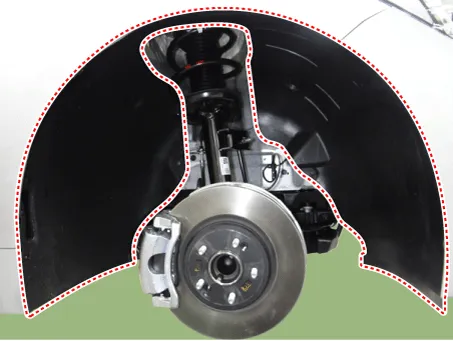
Remove wheel nuts, front wheel and tire (A) from hub.
|


| 2. |
Loosen the nut and then separate the stabilizer link from the front shock absorber.
|
| 3. |
Loosen the bolts (A) and then remove the stabilizer bar.
|
| 4. |
Remove the engine room side cover. D 2.2 R VGT (Refer to Engine Mechanical System - "Engine Room Under cover") G 2.0 T-GDI THETA II (Refer to Engine Mechanical System - "Engine Room Under cover") G 3.3 T-GDI LAMBDA II (Refer to Engine Mechanical System - "Engine Room Under cover") |
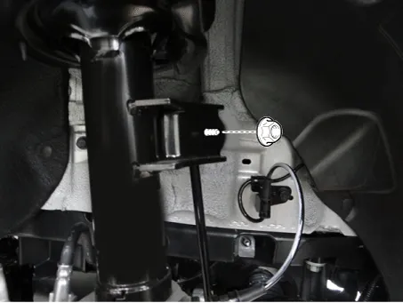
| 5. |
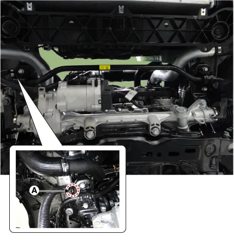
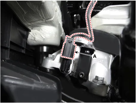
Disconnect the R-MDPS connector (A) and clip (B).
|
| 6. |
Loosen the shaft joint bolt (A) and then separate the shaft joint.
|
| 7. |
Disconnect the R-MDPS wiring clip (A) from the sub frame.
|
| 8. |
Remove the tie rod end nut.
|
| 9. |
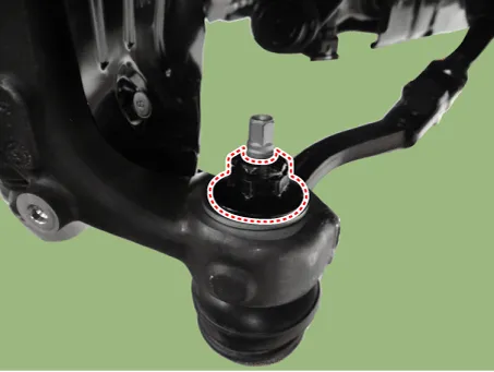
Remove the knuckle by using the ball joint remover (A).
|
| 10. |
Loosen the gear box bolts (A) and then remove the gear box.
|
| 11. |
Remove the front wheel guard.
|
| 12. |
Remove the lateral arm.
|
| 13. |
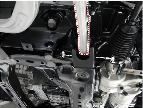
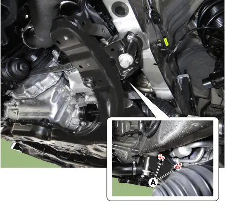
Loosen the compression arm bolt & nut from the subframe.
|
| 14. |
Remove the hood assembly. (Refer to Body - "Hood assembly") |
| 15. |
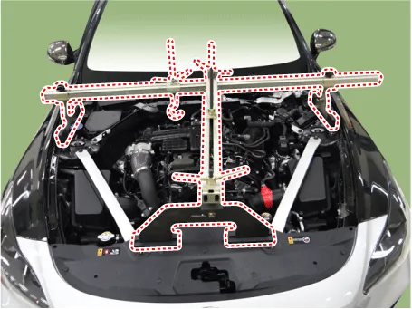
Assemble the engine support fixture on the engine room. (Refer to Special Service Tools - "Engine support fixture assembly drawing")
|
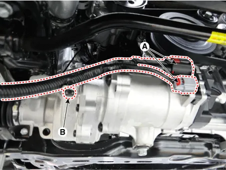
| 16. |
Disconnect the semi active engine mounting connector (A). [R 2.2] [LH]
[RH]
|
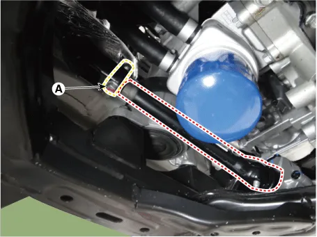
| 17. |
Loosen the intercooler inlet hose bolt. [R 2.2]
|

| 18. |
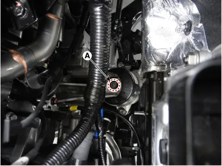
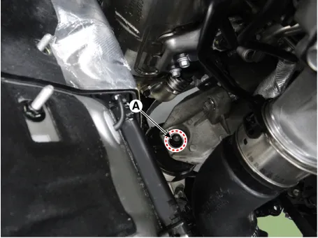
Loosen the engine mounting insulator nut (A).
[RH] [2.0 T-GDI THETA II, R 2.2]
[LH]
[3.3 T-GDI LAMBDA II]
|
| 19. |
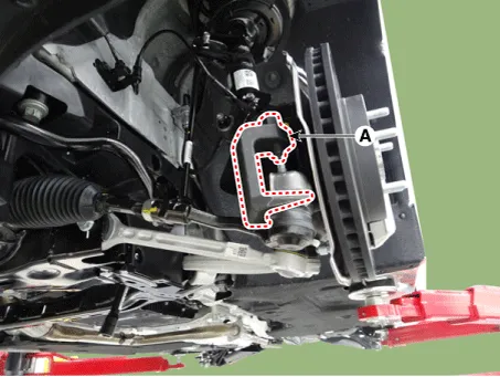
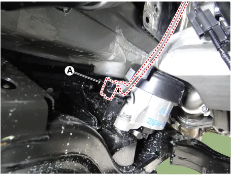
Remove the clip (A) from the sub frame. [3.3 T-GDI LAMBDA II]
|
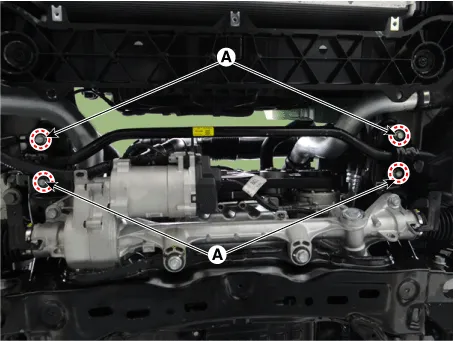
| 20. |
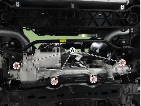
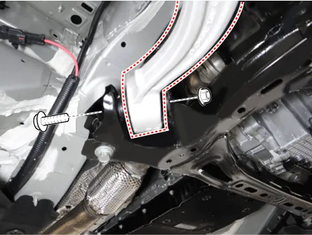
Loosen the bolts (A) and then remove the sub frame.
|
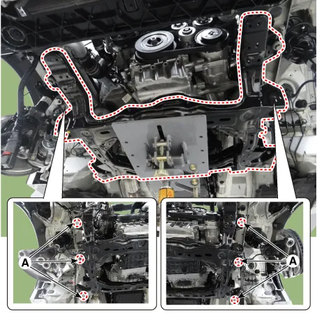
| 21. |
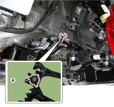
Remove the engine bracket from the sub frame.
|
| 22. |
Install in the reverse order of removal.
|
| 23. |
Check the front alignment. (Refer to Suspension System - "Alignment") |
[AWD]
| 1. |
Remove wheel nuts, front wheel and tire (A) from hub.
|
| 2. |
Remove the front wheel guard.
|
| 3. |
Remove the engine room side cover. D 2.2 R VGT (Refer to Engine Mechanical System - "Engine Room Under cover") G 2.0 T-GDI THETA II (Refer to Engine Mechanical System - "Engine Room Under cover") G 3.3 T-GDI LAMBDA II (Refer to Engine Mechanical System - "Engine Room Under cover") |
| 4. |
Remove the lateral arm.
|
| 5. |
Loosen the compression arm bolt & nut from the subframe.
|
| 6. |
Loosen the nut and then separate the stabilizer link from the front shock absorber.
|
| 7. |
Loosen the bolts (A) and then remove the stabilizer bar.
|
| 8. |
Disconnect the R-MDPS connector (A) and clip (B).
|
| 9. |
Loosen the shaft joint bolt (A) and then separate the shaft joint.
|
| 10. |
Disconnect the R-MDPS wiring clip (A) from the sub frame.
|
| 11. |
Loosen the gear box bolts (A) and then remove the gear box.
|
| 12. |
Remove the hood assembly. (Refer to Body - "Hood assembly") |
| 13. |
Assemble the engine support fixture on the engine room. (Refer to Special Service Tools - "Engine support fixture assembly drawing")
|
| 14. |
Disconnect the semi active engine mounting connector (A). [R 2.2] [LH]
[RH]
|
| 15. |
Loosen the intercooler inlet hose bolt. [R 2.2]
|
| 16. |
Loosen the engine mounting insulator nut (A).
[RH] [2.0 T-GDI THETA II, R 2.2]
[LH]
[3.3 T-GDI LAMBDA II]
|
| 17. |
Remove the clip (A) from the sub frame. [3.3 T-GDI LAMBDA II]
|
| 18. |
Loosen the bolts (A) and then remove the sub frame.
|
| 19. |
Remove the engine bracket from the sub frame.
|
| 20. |
Install in the reverse order of removal.
|
| 21. |
Check the front alignment. (Refer to Suspension System - "Alignment") |


Other information:
Kia Stinger (CK) 2018-2023 Service Manual: Cowl Side Trim
Components and components location Component Location 1. Cowl side trim Repair procedures Replacement Put on gloves to protect your hands. • When prying with a flat-tip screwdriver or using a prying trim tool, wrap protective tap around the tool and related parts to prevent damage.Kia Stinger (CK) 2018-2023 Service Manual: Audio Front Monitor
Components and components location Components Repair procedures Removal • When removing with a flat-tip screwdriver or remover, wrap protective tape around the tools to prevent damage to components. • When removing the interior trim pieces, use a plastic panel removal tool not to damage the surface.Categories
- Manuals Home
- Kia Stinger Owners Manual
- Kia Stinger Service Manual
- New on site
- Most important about car
