Kia Stinger CK: Driveshaft and axle / Rear Axle Assembly
Components and components location
| Components |
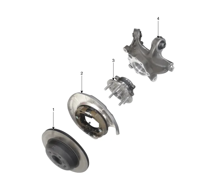
| 1. Rear brake disc 2. Hub assembly |
3. Dust cover 4. Rear knuckle |
Repair procedures
| Removal |
| 1. |
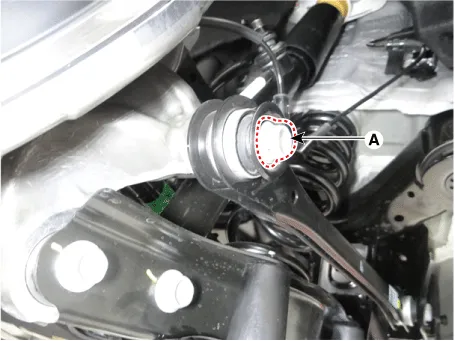
Remove wheel nuts, rear wheel and tire (A) from rear hub.
|


| 2. |
Remove the rear brake caliper. (Refer to Brake System - "Rear Disc Brake") |
| 3. |
Remove the split pin (A) from the rear hub and loosen the hub nut (B).
|

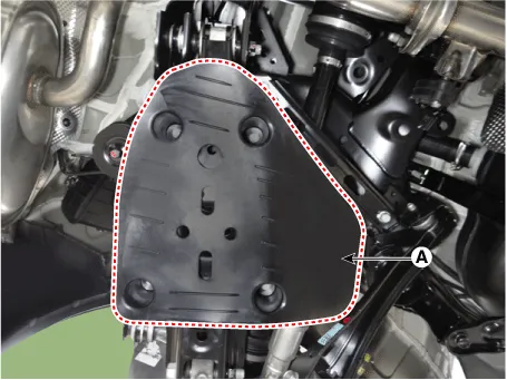
| 4. |
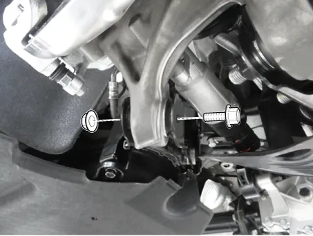
Remove the rear lower arm cover (A).
|
| 5. |
Remove the wheel speed sensor.
|

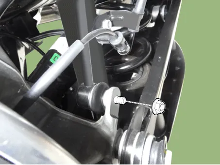
| 6. |
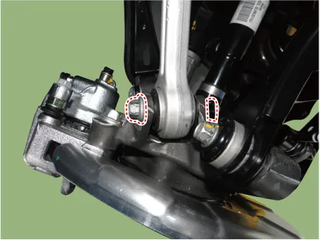
Loosen the stabilizer link nut and then separate the rear axle.
|
| 7. |
Loosen the rear lower arm bolt & nut and then separate the rear lower arm from the rear axle.
|
| 8. |
Loosen the nut & bolt and then separate the trailing arm from the rear axle.
|
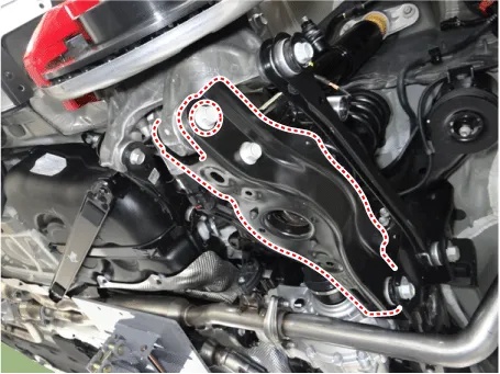
| 9. |
Loosen the bolt (A) and then separate the rear assist arm from the rear axle.
|
| 10. |
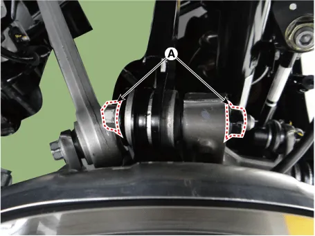
Loosen the bolt & nut and then remove the rear upper arm rear from the rear axle.
|
| 11. |
Loosen the rear upper arm rear bolt & nut (A) and then separate the rear upper arm rear.
|
| 12. |
Separate the rear drive shaft from the knuckle.
|

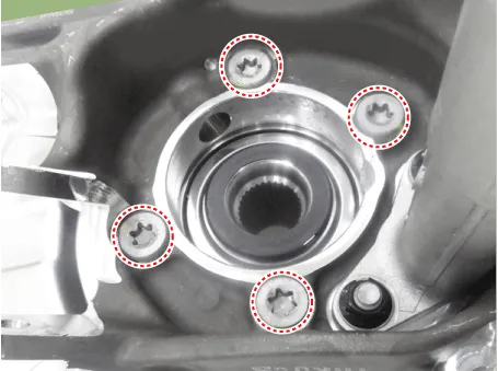
| 13. |
Loosen the bolts and then remove the rear hub assembly.
|
| 14. |
Install in the reverse order of removal. |
| 15. |
Check the rear alignment. (Refer to Suspension System - "Alignment") |
| Inspection |
| 1. |
Check the hub for cracks and the splines for wear. |
| 2. |
Check the rear axle carrier for cracks. |


Other information:
Kia Stinger (CK) 2018-2023 Service Manual: Mechanism Rail
Components and components location Components Location 1. Mechanism Rail Repair procedures Replacement Put on gloves to protect your hands. • Use a plastic panel removal tool to remove interior trim pieces without marring the surface.Kia Stinger (CK) 2018-2023 Service Manual: Forward Collision-Avoidance Assist (FCA) System
Description and operation Description – The Forward Collision-Avoidance Assist (FCA) radar sends a signal to detect the vehicle in front, based on the calculated distance the FCA applies the brakes in order to avoid or lessen collision with the vehicle in front due driver distraction or late braking response.Categories
- Manuals Home
- Kia Stinger Owners Manual
- Kia Stinger Service Manual
- New on site
- Most important about car
