
Kia Stinger CK: ISG (Idle Stop & Go) System / DC/DC Converter
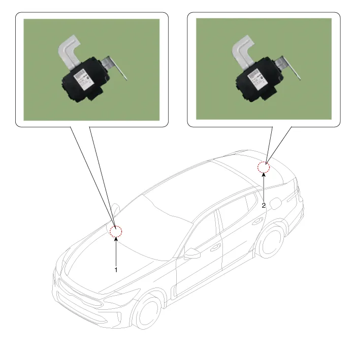
Components and components location
| Components Location |
Schematic diagrams
| Circuit Diagram |
| [200W] |
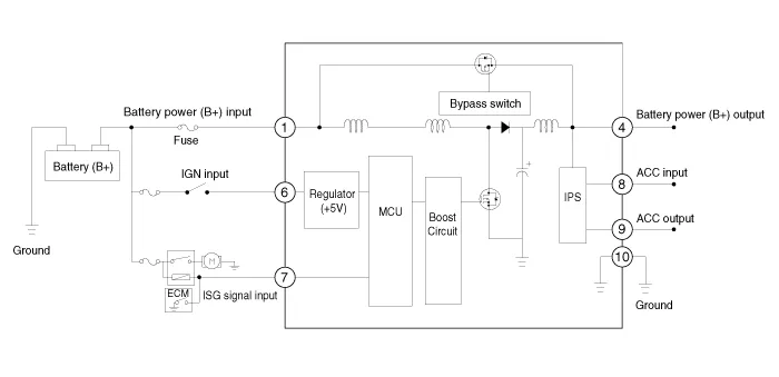
| [400W] |

| Terminal Function |
| [200W] |

|
PIn. |
Description |
PIn. |
Description |
|
1 |
Battery power (B+) input |
7 |
ISG signal input |
|
2 |
- |
8 |
ACC input |
|
3 |
- |
9 |
ACC output |
|
4 |
Battery power (B+) output |
10 |
Ground |
|
5 |
- |
11 |
- |
|
6 |
IGN1 input |
|
|
| [400W] |

|
PIn. |
Description |
PIn. |
Description |
|
1 |
Battery power (B+) input |
7 |
Battery power (B+) input |
|
2 |
- |
8 |
Battery power (B+) output |
|
3 |
Battery power (B+) output |
9 |
Battery power (B+) output |
|
4 |
Ground |
10 |
Ground |
|
5 |
IGN1 input |
11 |
ACC output |
|
6 |
ISG signal input |
12 |
ACC input |
Repair procedures
| Removal |
| [200W] |
| 1. |
Switch "OFF" the ignition and disconnect the negative (-) battery terminal. |
| 2. |
Remove the glove box housing. (Refer to Body (Interior and Exterior) - "Glove Box Housing") |
| 3. |
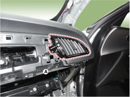
Remove the [RH] side air bant duct (A) after loosening the mounting screw.
|
| 4. |
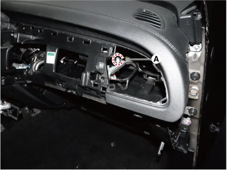
Remove the DC/DC converter after loosening the mounting bolt (A) and nut(B).
|
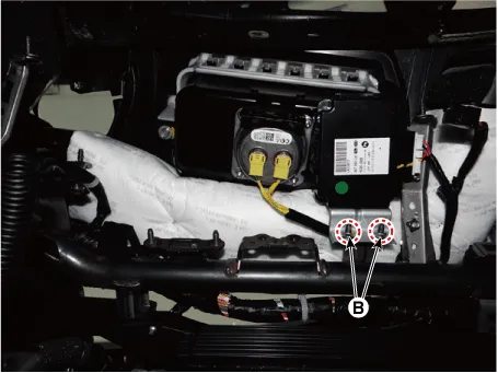
| [400W] |
| 1. |
Switch "OFF" the ignition and disconnect the negative (-) battery terminal. |
| 2. |
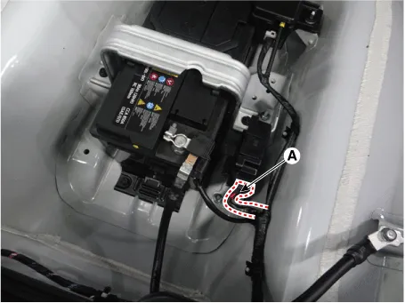
Disconnect the DC/DC converter connector (A).
|
| 3. |
Remove the DC/DC converter (A) after loosening the mounting nuts.
|

| Installation |
After reconnecting the battery negative cable, ISG function does not operates until the system is stabilized, about 4 hours. If disconnecting the negative (-) battery cable from the battery during repair work for the vehicle equipped with AMS function, Battery sensor recalibration procedure should be performed after finishing the repair work. |

| 1. |
Install in the reverse order of removal. |


Other information:
Kia Stinger (CK) 2018-2023 Service Manual: R Position Solenoid Valve (ON/OFF)
Specifications Specifications Item Specification Control type ON/OFF Control pressure kpa (kgf/cm², psi) 539.36 (5.5, 78.23) Current (mA) 0 - 600 Coil resistance (Ω) 10.5 ± 0.5 Components and components location Components Location 1.Repair procedures Inspection Troubleshooting of the speakers When handling the speakers : • Do not cause shock to the speakers by dropping or throwing them. • Be careful not to drop water and oil on the speakers.Categories
- Manuals Home
- Kia Stinger Owners Manual
- Kia Stinger Service Manual
- New on site
- Most important about car
