Other information:
Kia Stinger (CK) 2018-2023 Service Manual: Power Tailgate Latch
Repair procedures
Removal
1.
Disconnect the negative (-) battery terminal.
2.
Remove the tailgate trim.
(Refer to Body - "Tailgate Trim")
3.
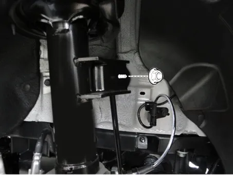
Disconnect the power tailgate latch connector (A) and power closing unit
connector (B).
4.
Kia Stinger (CK) 2018-2023 Service Manual: Emergency starting
Connect cables in numerical order and disconnect in reverse order.
Jump starting
Jump starting can be dangerous if done incorrectly. Therefore, to avoid harm
to yourself or damage to your vehicle or battery, follow these jump starting procedures.
If in doubt, we strongly recommend that you have a competent technician or towing
service jump start your vehicle.