
Kia Stinger CK: Cooling System / Cooling Fan
Components and components location
| Components |
[BLDC (Brushless DC) motor type]

| 1. Radiator 2. Cooling fan assembly |
3. Reservoir tank |
[DC motor type]
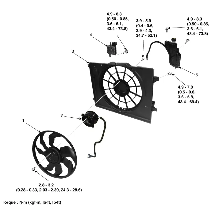
| 1. Cooling fan 2. Cooling fan motor 3. Cooling fan shroud |
4. Cooling fan controller 5. Reservoir tank |
Description and operation
| Description |
The cooling fan operates in 2 stages (HIGH/LOW). The engine control module (ECM) controls the cooling fan according to the coolant temperature, vehicle speed and A/C operation.
Specifications
| Specification |
[BLDC (Brushless DC) motor type]
|
Items |
Specification |
|
Fan type |
Puller |
|
Fan speed control method |
PWM |
|
Air flow rate [m³/h (yd³/h)] |
3,500 (4,578) - 8 % min. |
|
Fan speed (rpm) |
2,500 ± 8 % |
|
Current (A) |
46.0 + 10 % max. |
[DC motor type]
|
Items |
Specification |
|
Fan type |
Puller |
|
Fan speed control method |
PWM |
|
Air flow rate [m³/h (yd³/h)] |
2,600 (3,401) - 8 % min. |
|
Fan speed (rpm) |
2,000 ± 8 % |
|
Current (A) |
23.3 + 10 % max. |
Schematic diagrams
| Circuit Diagram |
[BLDC (Brushless DC) motor type]
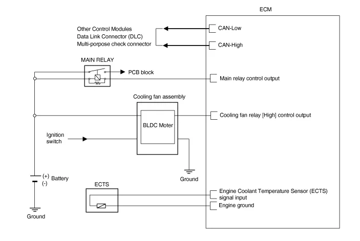
[DC motor type]
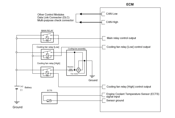
Repair procedures
| Removal and Installation |
Cooling Fan Assembly
| 1. |
Disconnect the negative battery terminal. |
| 2. |
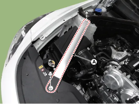
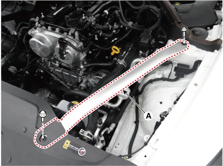
Remove the front strut bar (A). [RH]
[LH]
|
| 3. |
Remove the reservoir tank. (Refer to Cooling System - "Reservoir Tank") |
| 4. |
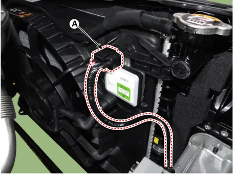
Disconnect the cooling fan connector (A). [BLDC (Brushless DC) motor type]
[DC motor type]
|

| 5. |
Remove the front bumper assembly. (Refer to body (Interior and Exterior) - "Front Bumper Assembly") |
| 6. |
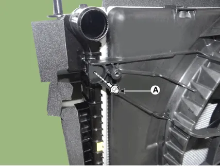
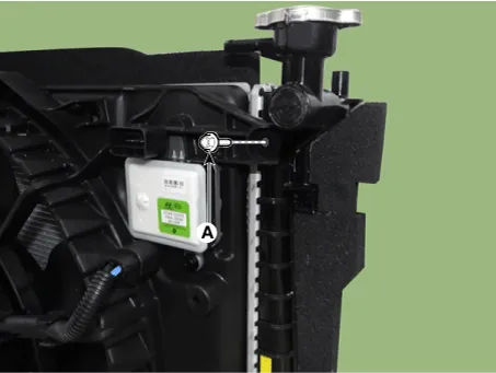
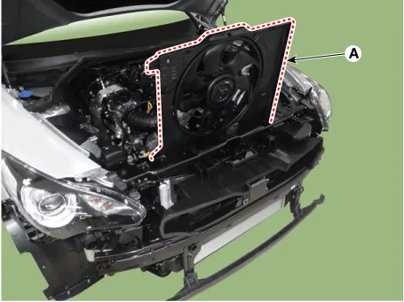
Remove the cooling fan assembly mounting bolts (A).
|
| 7. |
Remove the cooling fan assembly (A).
|
| 8. |
Install the other parts in the reverse order of removal. |
Cooling Fan Controller (PWM) [Only DC motor type]
| 1. |
Disconnect the negative battery terminal. |
| 2. |
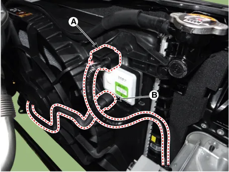
Disconnect the cooling fan controller (PWM) connector (A) and cooling fan motor connector (B).
|
| 3. |
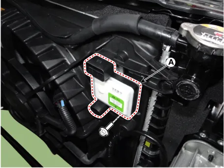
Remove the cooling fan controller (PWM) (A).
|
| 4. |
Install the other parts in the reverse order of removal. |
| Disassembly |
[Only DC motor type]
| 1. |
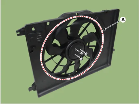
Remove the cooling fan (A) from the cooling fan assembly.
|
| 2. |
Disconnect the fan motor connector (A).
|
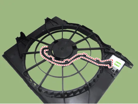
| 3. |
Remove the fan motor (A) from the cooling fan shroud.
|
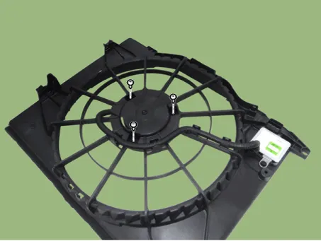
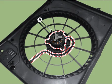
| 4. |
Assemble in the reverse order of disassembly. |
| Inspection |
Fan Motor
| 1. |
Disconnect the fan motor connector from the resistor. |
| 2. |
Connect the battery voltage to the "+" terminal and ground to "-" terminal. |
| 3. |
Check the cooling fan motor operates well. |


Other information:
Kia Stinger (CK) 2018-2023 Service Manual: Line Pressure Control Solenoid Valve (LINE_VFS)
Specifications Specifications Item Specification Control type N/L (Normal Low) Control pressure kpa (kgf/cm², psi) 0 - 519.75 (0 - 5.3, 0 - 75.38) Current (mA) 0 - 850 Coil resistance (Ω) 5.Kia Stinger (CK) 2018-2023 Service Manual: Knock Sensor (KS)
Specifications Specification Item Specification Capacitance (pF) 850 - 1,150 Resistance (MΩ) Approx. 1 Description and operation Description Knocking is a phenomenon characterized by undesirable vibration and noise that can cause engine damage.Categories
- Manuals Home
- Kia Stinger Owners Manual
- Kia Stinger Service Manual
- New on site
- Most important about car
