Kia Stinger CK: Windshield defrosting and defogging / Automatic climate control system
Contents:
To defog inside windshield
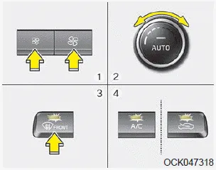
1. Set the fan speed to the desired position.
2. Select desired temperature.
3. Press the defroster button (
 ).
).
4. The outside (fresh) air position will be selected automatically and the air conditioning will turn on according to the detected ambient temperature.
If the air conditioning and outside (fresh) air position are not selected automatically,
adjust the corresponding button manually. If the
 position is selected, lower fan speed
is adjusted to a higher fan speed.
position is selected, lower fan speed
is adjusted to a higher fan speed.
To defrost outside windshield
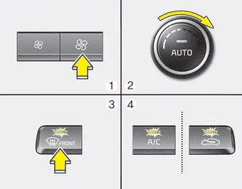
1. Set the fan speed to the highest position.
2. Set the temperature to the extreme hot (HI) position.
3. Press the defroster button (
 ).
).
4. The outside (fresh) air position will be selected automatically and the air conditioning will turn on according to the detected ambient temperature.


Other information:
Components and components location Component Location Front Seat Heater 1. Front seat heater unit (Assist seat only) 2. Front seat heater (Back) 3. Front seat heater (Cushion) Front Seat Heater (Air Ventilation) 1. Air ventilation seat unit (Assist seat only) 2.Repair procedures Removal and Installation 1. Remove the automatic transmission. (Refer to Automatic Transmission System - "Automatic Transmission") 2. Remove the drive plate adapter (A) and drive plate (B). Tightening torque : 117.7 - 127.5 N·m (12 - 13 kg·m, 86.Categories
- Manuals Home
- Kia Stinger Owners Manual
- Kia Stinger Service Manual
- New on site
- Most important about car
Contents
