Kia Stinger CK: Hydraulic System / 35R Clutch Control Solenoid Valve (35R/C_VFS)
Specifications
| Specifications |
|
Item |
Specification |
|
Control type |
N/H (Normal High) |
|
Control pressure kpa (kgf/cm², psi) |
0 - 1,569.06 (0 - 16, 0 - 227.57) |
|
Current (mA) |
0 - 1,100 |
|
Coil resistance (Ω) |
5.3 ± 0.3 |
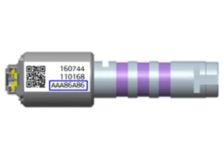
Components and components location
| Components Location |
| 1. 35R clutch control solenoid
valve |
2. Solenoid valve support bracket
|
Description and operation
| Description |
| • |
35R clutch control solenoid valve is a Variable Force Solenoid (VFS) type. |
| • |
When TCM supplies variable current to solenoid valve, hydraulic pressure of 35R clutch is controlled directly by solenoid valve. |

Solenoid Valve Operation Table
|
|
Solenoid Valve |
Clutch |
|
35R/C_VFS |
35R/C |
|
|
P |
|
|
|
N |
● |
|
|
1 |
● |
|
|
2 |
● |
|
|
3 |
|
● |
|
4 |
● |
|
|
5 |
|
● |
|
6 |
● |
|
|
7 |
● |
|
|
8 |
● |
|
|
REV |
|
● |
Schematic diagrams
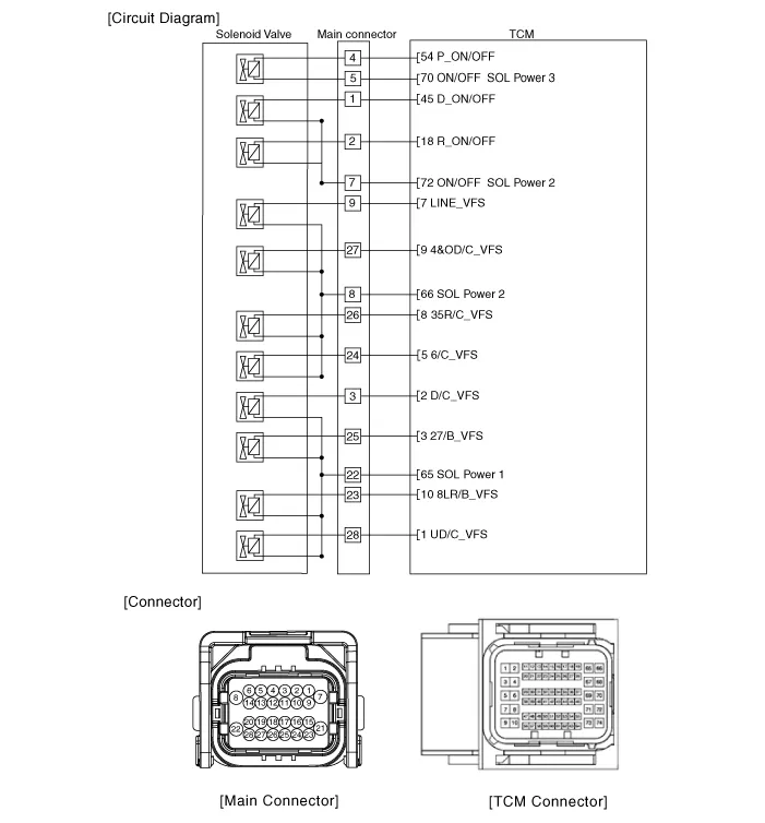
| Circuit Diagram |
Repair procedures
| Inspection |
| 1. |
Switch "OFF" ignition |
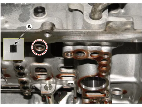
| 2. |
Disconnect the main connector (A).
|

| 3. |
Measure the resistance between power terminal (8) and signal terminal (26).
|
| Removal |
|

| 1. |
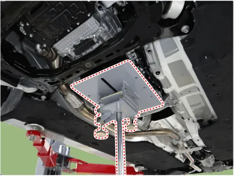
Remove the under cover. (Refer to Engine Mechanical System - "Engine Room Under Cover"). |
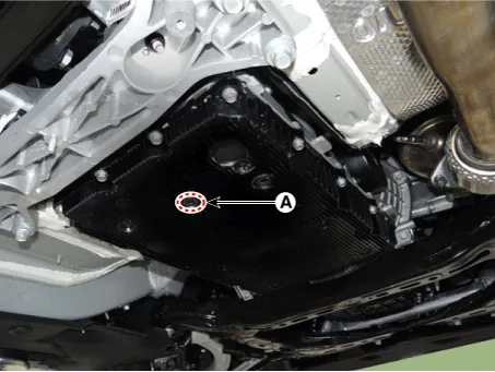
| 2. |
Remove the ATF drain plug (A), allow the fluid to drain out and then reinstall the drain plug.
|

| 3. |
Disconnect the main connector (A).
|
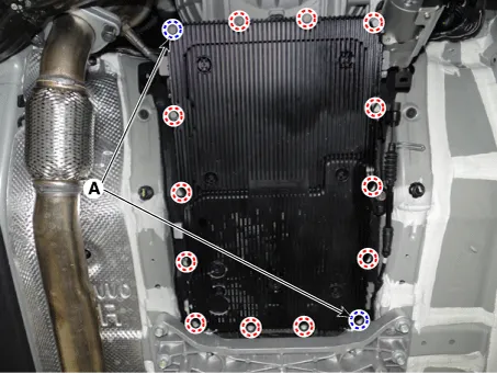
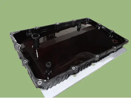
| 4. |
Remove the valve body cover.
|
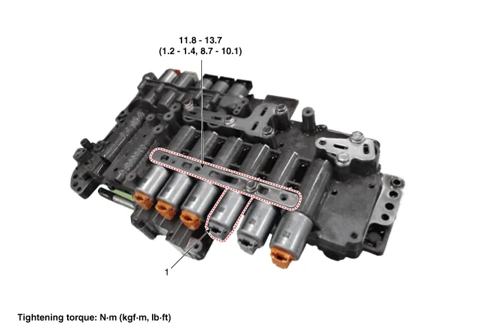
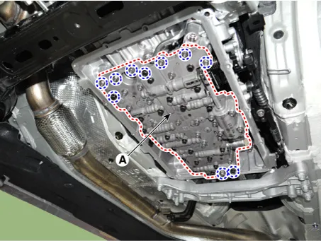
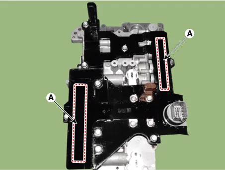
| 5. |
Remove the valve body assembly (A) after loosening the bolts.
|
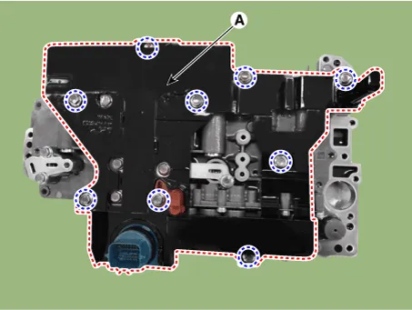
| 6. |
Remove the E-module (A) after loosening the bolts.
|
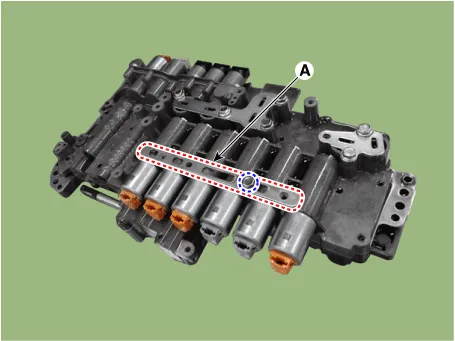
| 7. |
Remove the solenoid valve support bracket (A).
|
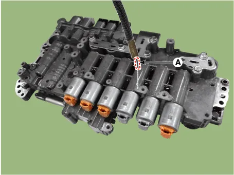
| 8. |
Remove the pin (A).
|
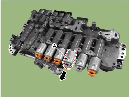
| 9. |
Remove the 35R clutch control solenoid vlave (A).
|
| Installation |
| 1. |
Install in the reverse order of removal.
|
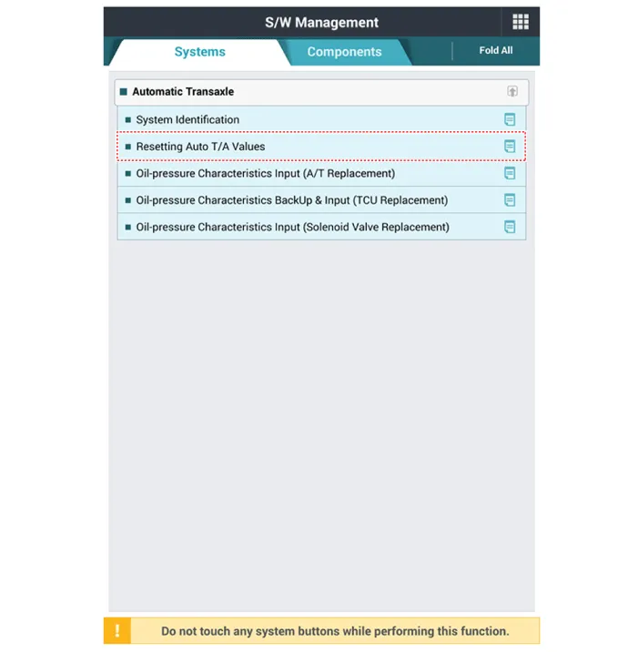
| 2. |
Perform the procedures below after installing.
|


Other information:
Kia Stinger (CK) 2018-2023 Service Manual: License Lamps
Repair procedures Removal 1. Disconnect the negative (-) battery terminal. 2. Remove the tailgate back panel. (Refer to Body - "Tailgate Back Panel") 3. Disconnect the license lamp connectors (A). 4. Remove the license lamp (A) after pressing the locking pin.Kia Stinger (CK) 2018-2023 Service Manual: Emergency liftgate safety release
Your vehicle is equipped with the emergency liftgate safety release lever located on the bottom of the liftgate. When someone is inadvertently locked in the luggage compartment, the liftgate can be opened by doing as follows: 1. Remove the cover. 2. Push the release lever to the right. 3. Push up the liftgate. WARNING For emergencies, be fully aware of the location of the emergency liftgate safety release lever in the vehicle and how to open the liftgate if you are accidentally locked in the luggage compartment.Categories
- Manuals Home
- Kia Stinger Owners Manual
- Kia Stinger Service Manual
- New on site
- Most important about car
