Kia Stinger CK: ISG (Idle Stop & Go) System / Alternator
Specifications
| Specification |
▷ 13.5V, 150A
|
Item |
Specification |
|
Rated voltage |
13.5V , 150A |
|
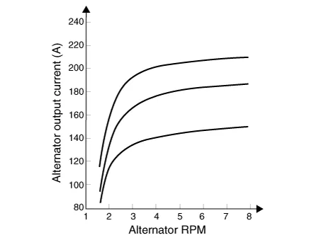
Speed in use |
0 - 18,000 rpm |
|
Pin |
1 |
|
Voltage regulator |
IC Regulator built in type |
|
Default regulated voltage (V) [COM terminal] |
14.39 - 15.43 [-35°C(31°F)] |
|
14.15 - 14.95 [25°C(77°F)] |
|
|
13.23 - 14.49 [140°C(284°F)] |
|
|
Pully Type |
OAP |
Description and operation
| Description |
The Alternator has eight built-in diodes, each rectifying AC current to DC current.
Therefore, DC current appears at alternator "B" terminal.
In addition, the charging voltage of this alternator is regulated by the battery voltage detection system.
The alternator is regulated by the battery voltage detection system.
The main components of the alternator are the rotor, stator, rectifier, capacitor brushes, bearings and V-ribbed belt pulley.
The brush holder contains a built-in electronic voltage regulator.
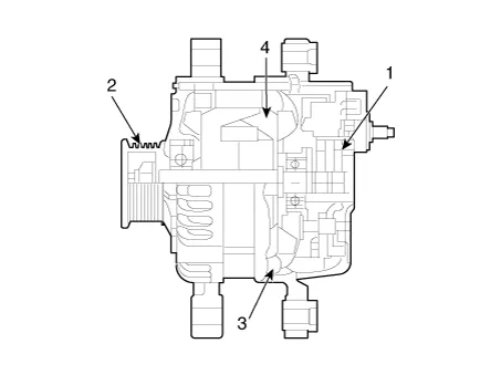
| 1. Brush 2. Drive belt pulley 3. Rotor 4. Stator |
Components and components location
| Components |
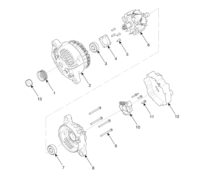
| 1. Pulley 2. Front bracket 3. Front bearing 4. Bearing cover 5. Bearing cover bolt 6. Rotor 7. Rear bearing |
8. Rear bracket8. Shield 9. Through bolt 10. Brush holder assembly 11. Brush holder bolt 12. Rear cover 13. Nut |
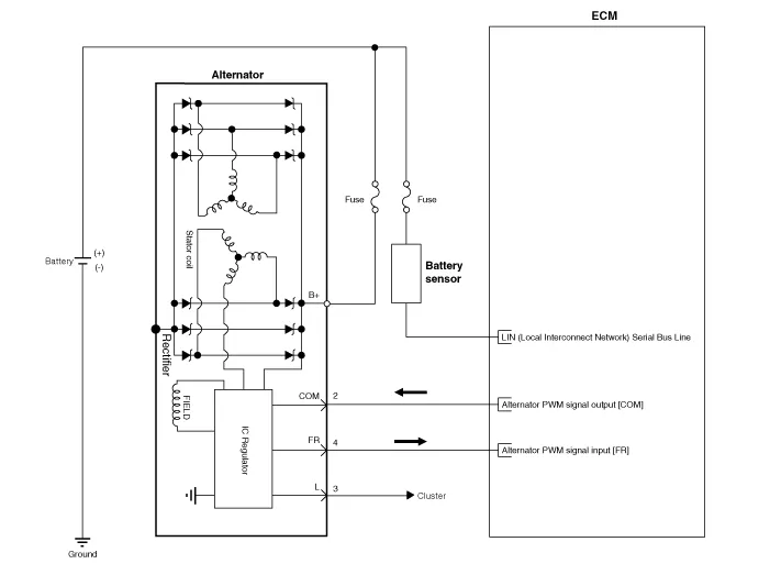
Schematic diagrams
| Circuit Diagram |
|

Repair procedures
| Removal |
| 1. |
Switch "OFF" the ignition and disconnect the negative (-) battery terminal. |
| 2. |
Remove the drive belt. (Refer to Engine Mechanical System - "Drive Belt") |
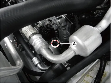
| 3. |
Disconnect the alternator connector (B), and remove the cable (A) from alternator "B" terminal.
|
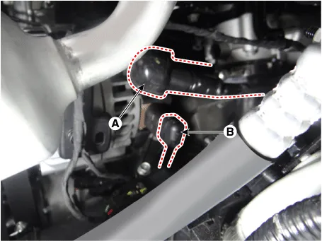
| 4. |
Remove the alternator lower bolt and upper bolt (A).
|

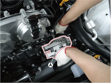
| 5. |
Remove the alternator (A).
|

| Installation |
| 1. |
Install in the reverse order of removal. |
| 2. |
Install the drive belt. (Refer to Engine Mechanical System - "Drive Belt") |


Other information:
Kia Stinger (CK) 2018-2023 Service Manual: Seat Belt Pretensioner (BPT)
Description and operation Description The Seat Belt Pretensioners (BPT) are installed inside the Center Pillars (LH & RH). When a vehicle crashes at a certain degree of frontal impact, the seat belt pretensioners help reduce the severity of injury to the front seat occupants by retracting the seat belt webbing. This prevents the front occupants from thrusting forward and hitting the steering wheel or the instrument panel when the vehicle crashes.Kia Stinger (CK) 2018-2023 Service Manual: Fuel Filler Door Open Switch
Components and components location Components Repair procedures Removal 1. Disconnect the negative (-) battery terminal. 2. Remove the crash pad lower panel. (Refer to Body - "Crash Pad Lower Panel") 3. Remove the crash pad garnish [LH] (A) after loosening the mounting screw.Categories
- Manuals Home
- Kia Stinger Owners Manual
- Kia Stinger Service Manual
- New on site
- Most important about car
