
Kia Stinger CK: Drive Belt System / Crankshaft Damper Pulley
Repair procedures
| Removal |
| 1. |
Remove the engine room front under cover. (Refer to Engine and Transmission Assembly - "Engine Room Under Cover") |
| 2. |
Remove the drive belt and water pump belt. (Refer to Drive Belt System - "Drive Belt") |
| 3. |
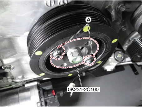
Install the SST (0K231-2C100) on the crankshatf damper pulley, and then tighten the bolts (A).
|
| 4. |
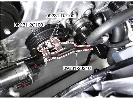
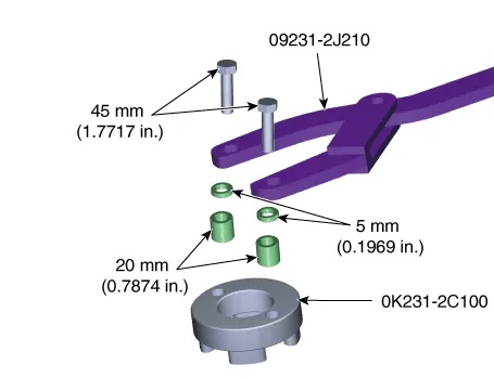
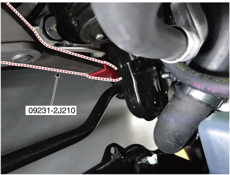
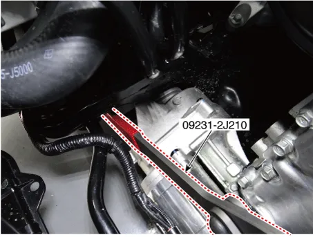
Install the SSTs (09231-2J210, 09231-D2100) on the SST (0K231-2C100) and then unfasten the crankshaft damper pulley mounting bolt.
|

| 5. |
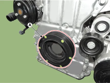
Remove the crankshaft damper pulley (A).
|
| Installation |
| 1. |
Install the crankshaft damper pulley (A).
|
| 2. |
Install the SST (0K231-2C100) on the crankshatf damper pulley, and then tighten the bolts (A).
|
| 3. |
Install the SSTs (09231-2J210, 09231-D2100) on the SST (0K231-2C100) and then tighten the crankshaft damper pulley mounting bolt.
|


| 4. |
Remove the SSTs (09231-2J210, 09231-D2100, 0K231-2C100) from the crankshaft damper pulley. |
| 5. |
Install the water pump belt and drive belt. (Refer to Drive Belt System - "Drive Belt") |
| 6. |
Install the engine room front under cover. (Refer to Engine and Transmission Assembly - "Engine Room Under Cover") |


Other information:
Kia Stinger (CK) 2018-2023 Service Manual: Cruise control system
The cruise control system allows you to program the vehicle to maintain a constant speed without depressing the accelerator pedal. This system is designed to function above approximately 30 km/h (20 mph ). If the cruise control is left on, (cruise indicator light is illuminated), the cruise control can be switched on accidentally. Keep the cruise control system off when the cruise control is not in use, to avoid inadvertently setting a speed.Kia Stinger (CK) 2018-2023 Service Manual: System malfunction
When the “Check System” warning message appears, the system is not working properly. In this case, have the vehicle inspected by an authorized Kia dealer. WARNING The Driver Attention Warning system is not a substitute for safe driving practices. It is the responsibility of the driver to always drive cautiously to prevent unexpected and sudden situations from occurring.Categories
- Manuals Home
- Kia Stinger Owners Manual
- Kia Stinger Service Manual
- New on site
- Most important about car
