Kia Stinger CK: Fuses / Fuse/relay panel description
Contents:
■ Driver’s side fuse panel

■ Engine compartment fuse panel
■ Rear fuse box panel
■ Battery box fuse panel
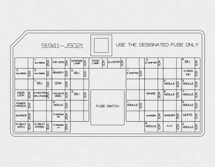
Inside the fuse/relay panel covers, you can find the fuse/relay label describing fuse/relay name and capacity.
✽ NOTICE
Not all fuse panel descriptions in this manual may be applicable to your vehicle. It is accurate at the time of printing. When you inspect the fuse panel in your vehicle, refer to the fuse panel label.
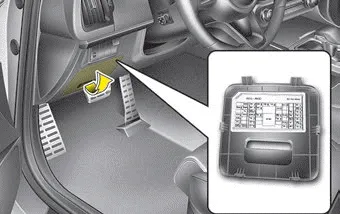
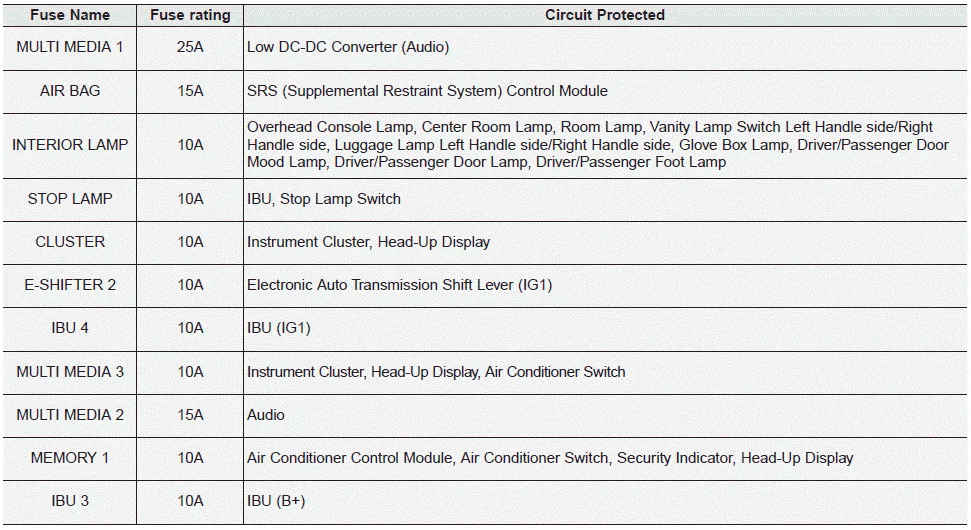
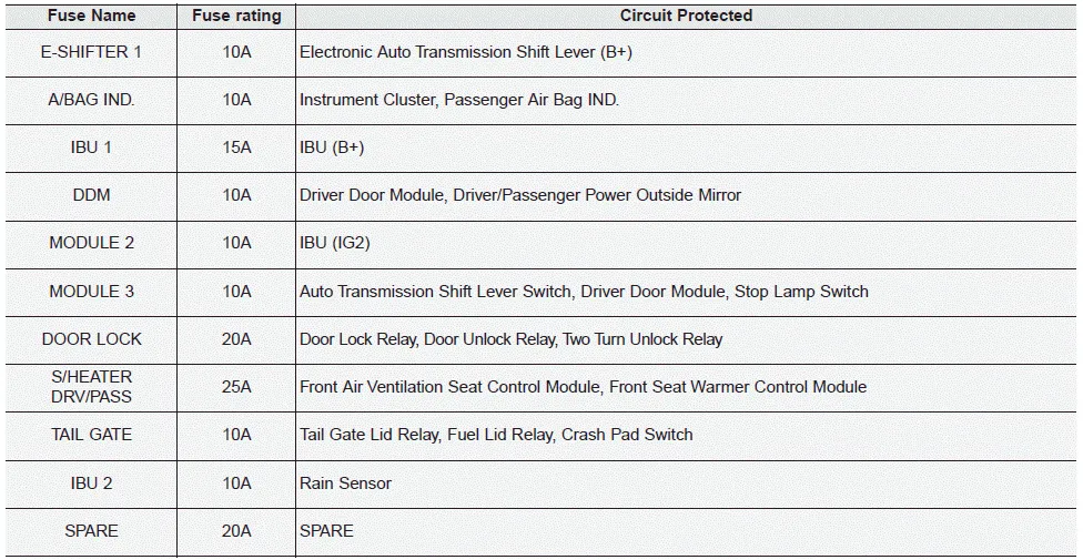
Driver’s side fuse panel
Instrument panel (Driver’s side fuse panel)
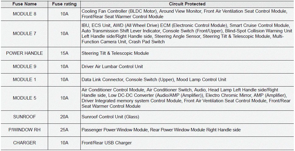

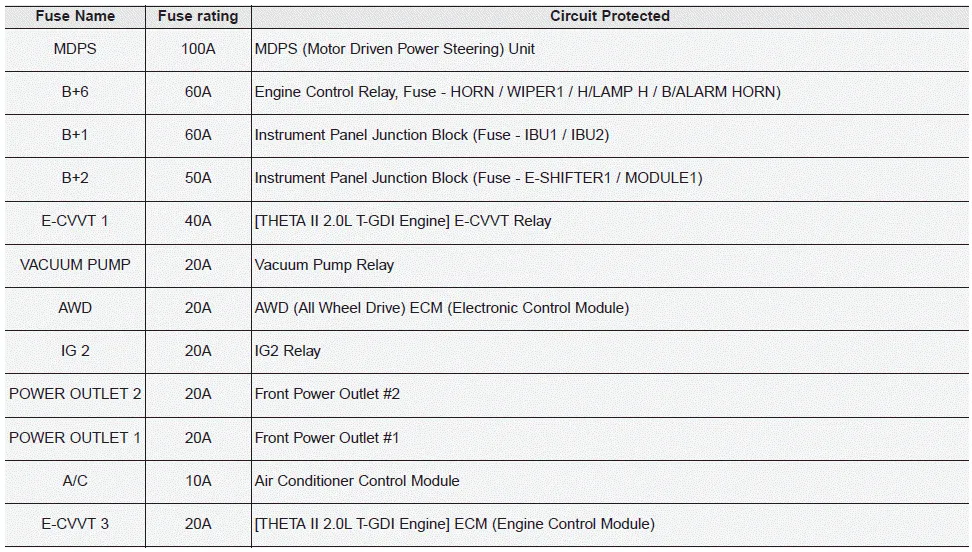
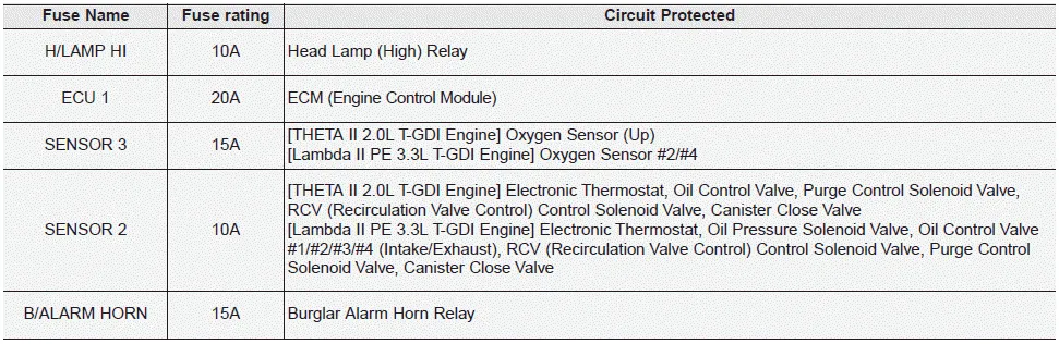
Engine compartment fuse panel
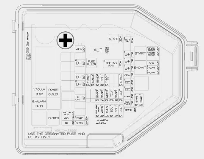
Engine room compartment fuse panel


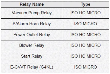
Relay
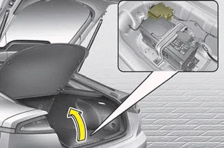
Rear fuse box panel
Rear fuse box panel

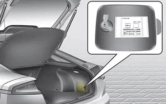
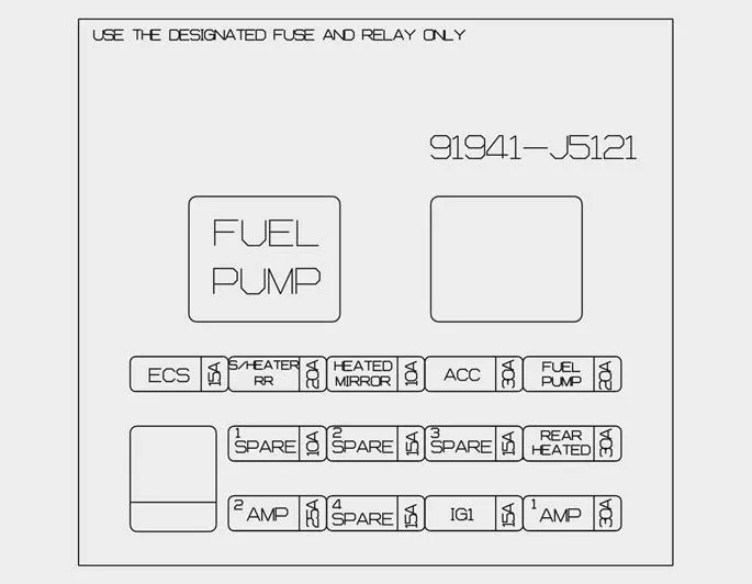
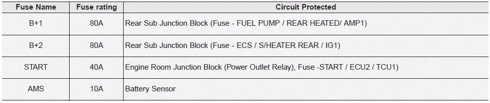
Battery box fuse panel
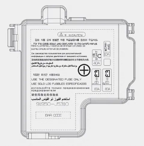
Battery box fuse panel


Other information:
Kia Stinger (CK) 2018-2023 Owner's Manual: Rear Lower Arm
Repair procedures Removal 1. Remove wheel nuts, wheel and tire (A) from hub. Tightening torque: 107.9 - 127.5 N·m (11.0 - 13.0 kgf·m, 79.6 - 94.0 lb·ft) Be careful not to damage the wheel bolts when removing the wheel and tire (A).Kia Stinger (CK) 2018-2023 Owner's Manual: Steering Column and Shaft
Repair procedures Replacement [LHD] 1. Disconnect the battery negative cable. 2. Turn the steering wheel so that the front wheels are facing straight ahead. 3. Remove the driver airbag. (Refer to Restraint - "Driver Airbag (DAB) Module and Clock Spring") 4.Categories
- Manuals Home
- Kia Stinger Owners Manual
- Kia Stinger Service Manual
- New on site
- Most important about car
Contents

Copyright © 2026 www.kstinger.com 0.0068