Kia Stinger CK: Engine Control System / E-CVVT motor
Components and components location
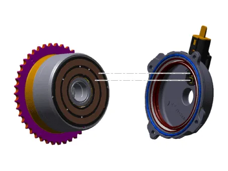
| Components |
Appearance of E-CVVT is similar to that of hydraulic CVVT. Connector that drives DC motor and protection cover that protects the motor are mounted on the upper part. DC motor that drives the CVVT is mounted inside and covering part is sealed in order to protect oil from flowing inside.

Description and operation
| Description |
E-CVVT (Electric Continuous Variable Valve Timing) system, located on the intake camshaft of the engine, uses motor rotation to control the rotation angle of camshaft relative to the rotation of crankshaft regardless of engine pressure. E-CVVT controls the DC motor current (duty signal) to more closely control the system compared to the previous pressure type, to increase reaction speed of cam, to improve startability, and to reduce the emission of exhaust gas. Also, operation range of intake valve (valve opening angle) is expanded. So, the output and fuel efficiency are improved.
| Operation |

Schematic diagrams
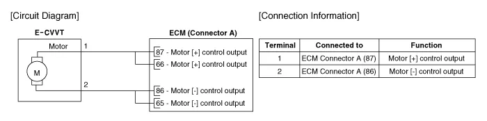
| Circuit diagram |
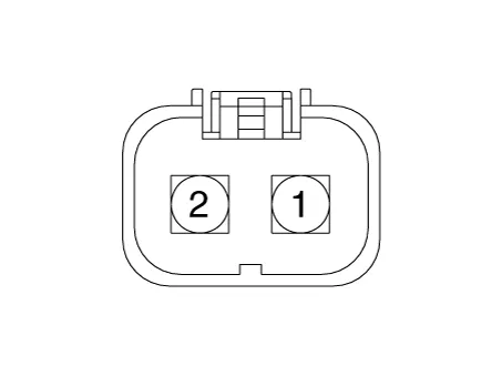
Harness Connector
Repair procedures
| Removal |
| 1. |
Remove the E-CVVT. (Refer to Engine Mechanical system - "CVVT & Camshaft") |
| Installation |
| 1. |
Mount the E-CVVT. (Refer to Engine Mechanical system - "CVVT & Camshaft") |
| Adjustment |
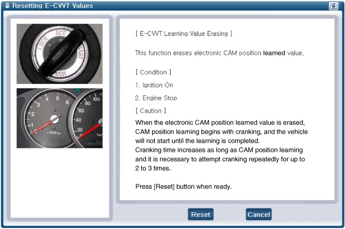
After replacing or remounting the E-CVVT assembly, be sure to reset the learned value from the additional feature menu on the KDS diagnostic device. When the learned value for electronic cam position is erased, start learning the cam position while cranking. The engine can start once this is completed. Cranking should be repeated for up to 2-3 times to complete learning.
|

Troubleshooting
| Signal Waveform |
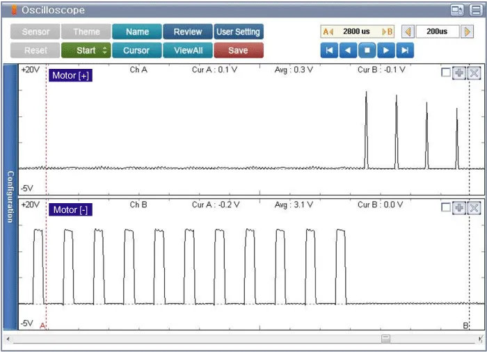
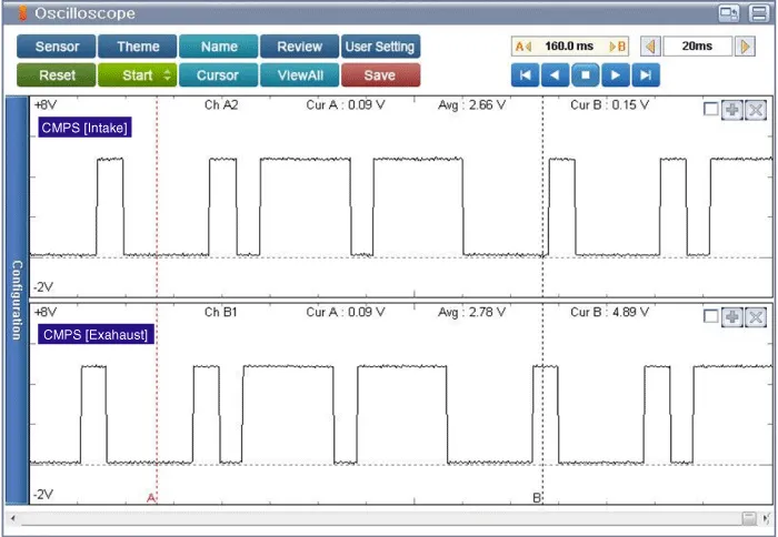
| • |
There is no separate sensor inside E-CVVT. Valve timing is calculated by applying 4-flank type target wheel on the exhaust side and comparing CKPS and CMPS. |


Other information:
Kia Stinger (CK) 2018-2023 Service Manual: Heater Core
Repair procedures Replacement 1. Disconnect the negative (-) battery terminal. 2. After loosening the nuts and bolts, remove the main crash pad and cowl cross bar assembly altogether. (Refer to Heater - "Heater Unit") 3. Remove the heater core (A). 4.Kia Stinger (CK) 2018-2023 Service Manual: Engine Room Under Cover
Repair procedures Removal and Installation Engine Room Front Under Cover. 1. Remove the engine room front under cover (A). Tightening torque : 7.8 - 11.8 N·m (0.8 - 1.2 kgf·m, 5.8 - 8.7 lb·ft) 2. Install in the reverse order of removal. Engine Room Rear Under Cover.Categories
- Manuals Home
- Kia Stinger Owners Manual
- Kia Stinger Service Manual
- New on site
- Most important about car
