Kia Stinger CK: Engine And Transmission Assembly / Engine Mounting
Components and components location
| Components |
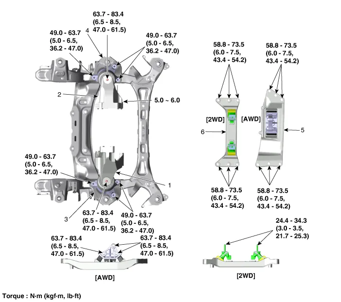
| 1. Engine mounting support bracket
(LH) 2. Engine mounting support bracket (RH) 3. Engine mounting bracket (LH) |
4. Engine mounting bracket (RH)
5. Transmission mounting bracket (AWD) 6. Transmission mounting bracket (2WD) |
Repair procedures
| Removal and Installation |
Engine Mounting Bracket
| 1. |
Remove the engine room front under cover and engine room side cover. (Refer to Engine and Transmission Assembly - "Engine Room Under Cover") |
| 2. |
Disconnect the universal joint assembly from the shaft joint. (Refer to Steering System - "Steering Column and Shaft") |
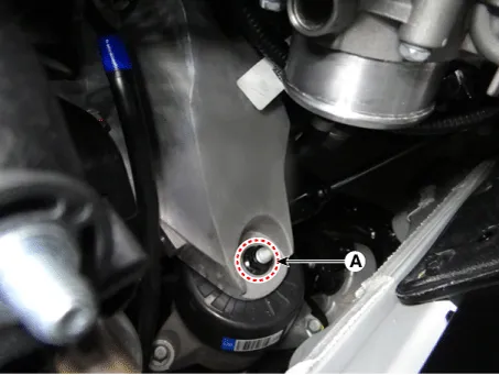
| 3. |
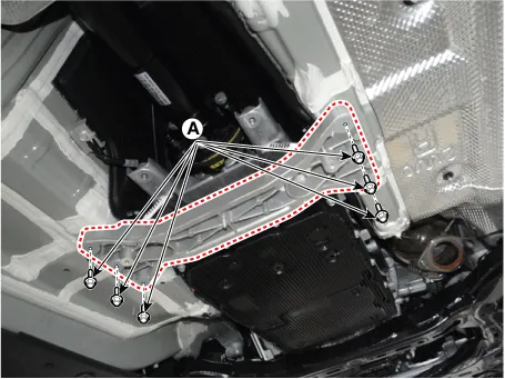
Remove the engine mounting support bracket nut (A).
[LH]
[RH]
|
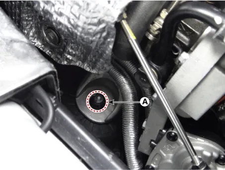
| 4. |
Install the jack to the edge of the oil pan to support the engine.
|


| 5. |
Lift the engine slightly using the jack to obtain space for removing the engine mounting. |
| 6. |
Remove the engine mounting bracket (A).
[LH]
[RH]
|


| 7. |
Install in the reverse order of removal. |
Transmission mounting bracket (AWD)
| 1. |
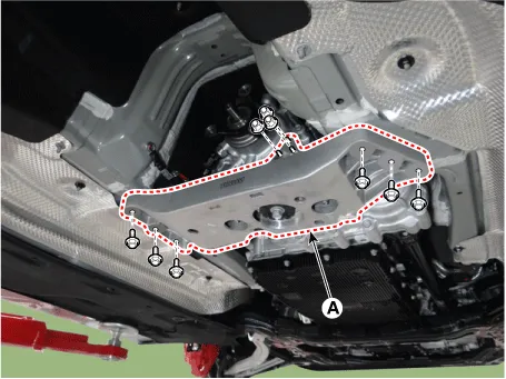
Remove the engine room rear under cover. (Refer to Engine and Transmission Assembly - "Engine Room Under Cover") |
| 2. |
Install the jack under the transmission to support the transmission.
|

| 3. |
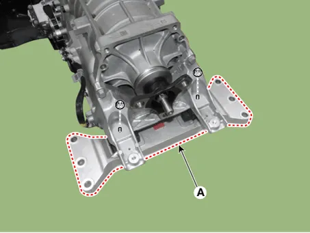
Remove the transmission mounting bracket (A).
|
| 4. |
Install in the reverse order of removal. |
Transmission mounting bracket (2WD)
| 1. |
Remove the engine room rear under cover. (Refer to Engine and Transmission Assembly - "Engine Room Under Cover") |
| 2. |
Install the jack under the transmission to support the transmission.
|
| 3. |
Remove the transmission mounting bracket mounting bolts (A).
|
| 4. |
Remove the transmission mounting bracket (A).
|
| 5. |
Install in the reverse order of removal. |


Other information:
Kia Stinger (CK) 2018-2023 Service Manual: Cooling Fan
Components and components location Components [BLDC (Brushless DC) motor type] 1. Radiator 2. Cooling fan assembly 3. Reservoir tank [DC motor type] 1. Cooling fan 2. Cooling fan motor 3. Cooling fan shroud 4. Cooling fan controller 5. Reservoir tank Description and operation Description The cooling fan operates in 2 stages (HIGH/LOW).Kia Stinger (CK) 2018-2023 Service Manual: Knee Airbag (KAB) Module
Description and operation Description Installed inside the crash pad, the knee airbag (KAB) protects the driver in the event of a frontal crash. The SRSCM determines if and when to deploy the KAB. Never attempt to measure the circuit resistance of the airbag module (squib) even if you are using a specified tester.Categories
- Manuals Home
- Kia Stinger Owners Manual
- Kia Stinger Service Manual
- New on site
- Most important about car
