Kia Stinger CK: Front Driveshaft Assembly / Front Driveshaft
Components and components location
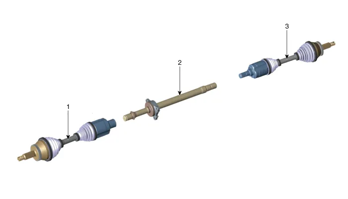
1. Front drive shaft [LH]
2. Front drive shaft bracket
|
3. Front drive shaft [RH]
|
Repair procedures
[3.3 T-GDI LAMBDA II
(LH)]
| 1. |
Remove wheel nuts, front wheel and tire (A) from front hub.
|
Tightening torque:
107.9 - 127.5 N·m (11.0 - 13.0 kgf·m, 79.6 - 94.0 lb·ft)
|

|
Be careful not to damage the wheel nuts when removing the front
wheel and tire (A).
|
|
| 2. |
Separate the air con compressor.
(Refer to Heating,Ventilation And Air Conditioning - "Compressor")
|
| 3. |
Remove the front brake caliper.
(Refer to Brake System - "Front Disc Brake")
|
| 4. |
By hammering on a chisel, unlock the drive shaft lock hub nut caulking.
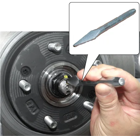
|
If there is screw thread (A) on the end of the nut, unlock the
caulking by using a chisel and then loosen the nut to prevent damaging
driveshaft screw thread.
|
|
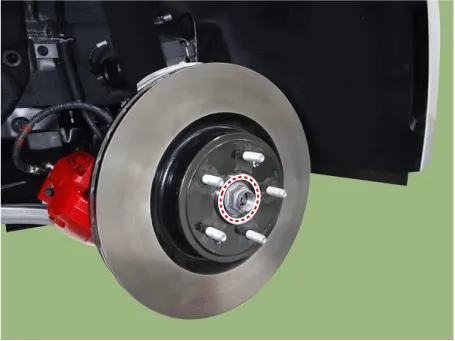
| 5. |
Loosen the caulking nut and then separate the hub assembly from the drive
shaft.
|
Tightening torque :
294.2 - 313.8 N·m (30.0 - 32.0 kgf·m, 217.0 - 231.5 lb·ft)
|
| •
|
Use plastic hammer to avoid damaging on axle when the
drive shaft is disassembled.
|
| •
|
Do not pull or twist excessively to remove the axle when
the drive shaft is disassembled.
|
|
|
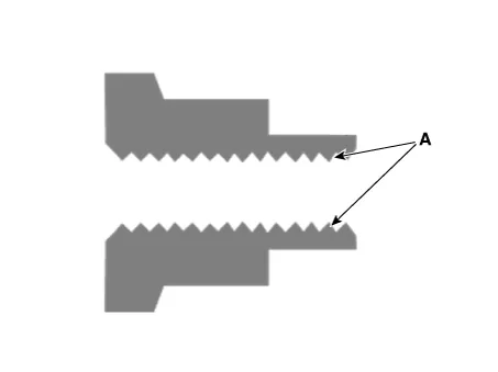
The driveshaft lock nut must be replaced with new one.
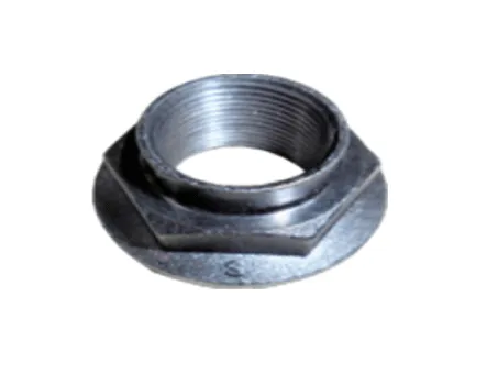
When replacing the drive lock hub nut, use only the nut with
screw thread (A) on the end.
| •
|
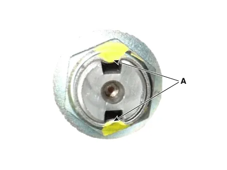
Tighten the driveshaft lock hub nut to the specified
tightening torque, and caulk by using a chisel and hammer.
|
| •
|
If there are two key seats, perform on all two seats.
Caulking depth (A) : 1.5 mm (0.0591 in)
|
|
|
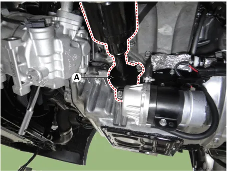
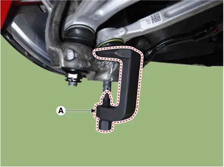
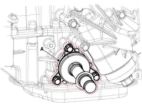
| 6. |
Remove the front drive shaft bracket (A) from the front differential
and then using pry bar, remove the front drive shaft [LH].
|
Tightening torque :
49.0 - 63.7 N·m (5.0 - 6.5 kgf·m, 36.2.0 - 47.0 lb·ft)
|
|
| 7. |
Install in the reverse order of removal.
| •
|
Use a pry bar being careful not to damage the transaxle
and joint.
|
| •
|
Do not insert the pry bar too deep, as this may cause
damage to the oil seal.
|
| •
|
Do not pull the driveshaft by excessive force it may
cause components inside the joint kit to dislodge resulting
in a torn boot or a damaged bearing.
|
| •
|
Plug the hole of the transaxle case with the oil seal
cap to prevent contamination.
|
| •
|
Support the driveshaft properly.
- Be careful that the drive shaft is not bent or drop
down by other component's weight (such as axle etc.)
|
| •
|
Replace the retainer ring whenever the driveshaft is
removed from the transaxle case.
|
|
|
| 8. |
Check the front alignment.
(Refer to Suspension System - "Alignment")
|
[2.0 T-GDI THETA II,
R 2.2(RH,LH)]
[3.3 T-GDI LAMBDA II
(RH)]
| 1. |
Remove wheel nuts, front wheel and tire (A) from front hub.
|
Tightening torque:
107.9 - 127.5 N·m (11.0 - 13.0 kgf·m, 79.6 - 94.0 lb·ft)
|
|
Be careful not to damage the wheel nuts when removing the front
wheel and tire (A).
|
|
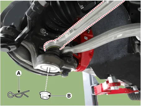
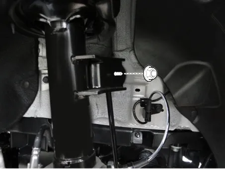
| 2. |
Loosen the lateral arm pin (A) and nut (B).
|
Tightening torque:
88.3 - 107.9 N·m (9.0 - 11.0 kgf·m, 65.1 - 79.6 lb·ft)
|
|
| 3. |
Remove the rateral arm by using the ball joint remover (A).
|
| 4. |
Loosen the compression arm pin (A) and nut (B).
|
Tightening torque :
88.3 - 107.9 N·m (9.0 - 11.0 kgf·m, 65.1 - 79.6 lb·ft)
|
|
| 5. |
Remove the compression arm by using the ball joint remover (A).

|
| 6. |
Loosen the nut and then separate the stabilizer link from the front shock
absorber.
|
Tightening torque :
98.1 - 117.7 N·m (10.0 - 12.0 kgf·m, 72.3 - 86.8 lb·ft)
|
|
| 7. |
By hammering on a chisel, unlock the driveshaft lock hub nut caulking.
|
If there is screw thread (A) on the end of the nut, unlock the
caulking by using a chisel and then loosen the nut to prevent damaging
driveshaft screw thread.
|
|
| 8. |
Loosen the caulking nut and then separate the hub assembly from the drive
shaft.
|
Tightening torque :
294.2 - 313.8 N·m (30.0 - 32.0 kgf·m, 217.0 - 231.5 lb·ft)
|
| •
|
Use plastic hammer to avoid damaging on axle when the
drive shaft is disassembled.
|
| •
|
Do not pull or twist excessively to remove the axle when
the drive shaft is disassembled.
|
|
|
The driveshaft lock nut must be replaced with new one.
When replacing the drive lock hub nut, use only the nut with
screw thread (A) on the end.
| •
|
Tighten the driveshaft lock hub nut to the specified
tightening torque, and caulk by using a chisel and hammer.
|
| •
|
If there are two key seats, perform on all two seats.
Caulking depth (A) : 1.5 mm (0.0591 in)
|
|
|
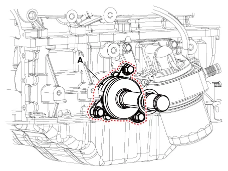
| 9. |
Remove the front drive shaft bracket (A). [LH]
|
Tightening torque :
49.0 - 63.7 N·m (5.0 - 6.5 kgf·m, 36.2.0 - 47.0 lb·ft)
|
[2.0 T-GDI
THETA II]
[R 2.2]
|
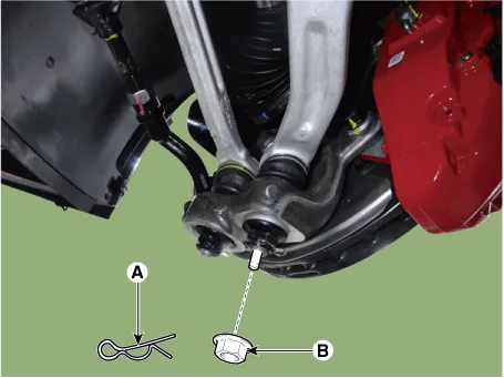
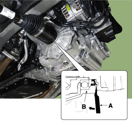
| 10. |
Using pry bar (A), separate the front drive shaft from the front differential
(B).
| •
|
Use a pry bar being careful not to damage the transaxle
and joint.
|
| •
|
Do not insert the pry bar too deep, as this may cause
damage to the oil seal.
|
| •
|
Do not pull the driveshaft by excessive force it may
cause components inside the joint kit to dislodge resulting
in a torn boot or a damaged bearing.
|
| •
|
Plug the hole of the transaxle case with the oil seal
cap to prevent contamination.
|
| •
|
Support the driveshaft properly.
- Be careful that the drive shaft is not bent or drop
down by other component's weight (such as axle etc.)
|
| •
|
Replace the retainer ring whenever the driveshaft is
removed from the transaxle case.
|
|
|
| 11. |
Install in the reverse order of removal.
|
Other information:
Kia Stinger (CK) 2018-2023 Service Manual: Receiver-Drier
Repair procedures
Replacement
1.
Remove the condenser.
2.
Remove the cap (B) from the bottom of the condenser using an L wrench
(A).
Tightening torque :
9.8 - 14.7 N·m (1.0 - 1.5 kgf·m, 7.2 - 10.8 lb·ft)
3.
Remove the receiver-drier (A) from condenser using long nose pliers.
Kia Stinger (CK) 2018-2023 Service Manual: Fluid (ATF)
Repair procedures
Automatic Transmission Fluid
(ATF) Level Check
1.
Start the engine to warm up the ATF.
Do not step on the brake and accelerator simultaneously to warm
up the ATF.
2.


