Kia Stinger CK: Front Driveshaft Assembly / TJ Joint
Repair procedures
| Replacement |
|

| 1. |
Remove the Front Driveshaft. (Refer to Driveshaft Assembly - “Front Driveshaft”) |
| 2. |
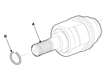
Remove the BJ circlip (B) from the TJ housing (A).
|
| 3. |
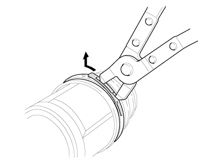
Remove both boot bands from the TJ housing.
|
| 4. |
Remove the TJ circlip (A).
|
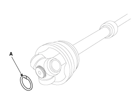
| 5. |
Remove the snap ring (A) from the shaft.
|
| 6. |
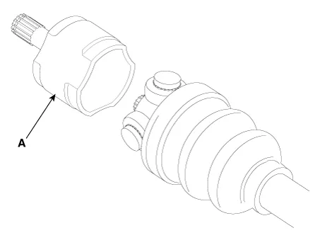
Clean the spider assembly. |
| 7. |
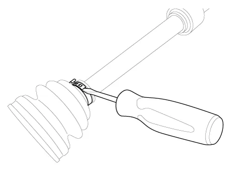
Remove the TJ boot (A).
|
| Inspection |
| 1. |
Check the spider assembly for roller rotation, wear or corrosion. |
| 2. |
Check the groove inside the joint case for wear or corrosion |
| 3. |
Check the TJ boots for damage and deterioration. |
| Installation |
| 1. |
Wrap tape around the driveshaft spline(TJ) to prevent damage to the boot. |
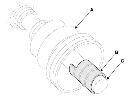
| 2. |
Using the alignment marks (D) made during disassembly as a guide, install the spider assembly (A) and snap ring (B) on the driveshaft splines (C).
|


| 3. |
Add specified grease to the joint boot as much as it was wiped away at inspection. |
| 4. |
Install the both boot band. |
| 5. |
To control the air in the TJ boot, keep the specified distance between the boot bands when they are tightened.
|
||||||||||||||

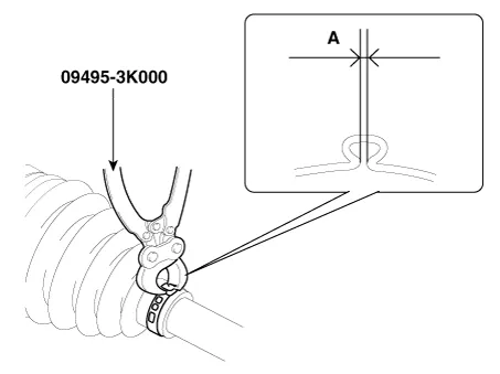
| 6. |
Using the SST(09495-3K000), secure the TJ boot bands.
|
| 7. |
Install the Front Driveshaft. (Refer to Driveshaft Assembly - “Front Driveshaft”) |
| 8. |
Check the front alignment. (Refer to Suspension System - "Alignment") |


Other information:
Kia Stinger (CK) 2018-2023 Service Manual: Steering Gear box
Components and components location Components 1. Tie rod end 2. R-MDPS motor Repair procedures Removal 1. Remove wheel nuts, front wheel and tire (A) from hub. Tightening torque : 107.9 - 127.5 N·m (11.0 - 13.0 kgf·m, 79.6 - 94.0 lb·ft) Be careful not to damage the wheel bolts when removing the wheel and tire (A).Repair procedures Hub nut tightening sequence Tighten the hub nuts as follows. Tightening torque: 107.9 - 127.5 N·m (11.0 - 13.0 kgf·m, 79.6 - 94.0 lb·ft) When using an impact gun, final tightening torque should be checked using a torque wrench.Categories
- Manuals Home
- Kia Stinger Owners Manual
- Kia Stinger Service Manual
- New on site
- Most important about car
