Kia Stinger CK: Fuel Delivery System / Fuel Pressure Sensor (FPS)
Specifications
| Specification |
|
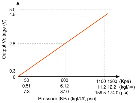
Pressure [kPa (kgf/cm², psi)] |
Output Voltage (V) [Vref = 5V] |
|
50 (0.51, 7.3) |
0.3 |
|
600 (6.12, 87.0) |
2.5 |
|
1100 (11.2, 159.5) |
4.5 |
Description and operation
| Description |
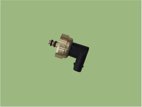
Installed on top of the low pressure fuel pump, the fuel pressure sensor (FPS) measures the pressure in the low pressure line.
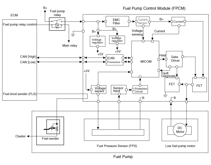
Based on the fuel pressure measured by the FPS and the fuel consumption, the fuel pump control module (FPCM) determines whether to activate the low pressure fuel pump.
After activating the low pressure fuel pump, the FPS continues to send the fuel pressure to the FPCM and the FPCM keeps controlling the fuel flow rate using the feedback from the FPS.
Schematic diagrams
| Circuit Diagram |
| Terminal Information |
| Terminal Illustration |

| Terminal Function |
|
No. |
Function |
Connected to |
|
1 |
Fuel Pressure sensor (FPS) power supply |
Fuel Pressure sensor (FPS) |
|
2 |
Fuel Pressure sensor (FPS) ground |
Fuel Pressure sensor (FPS) |
|
3 |
Fuel Pressure sensor (FPS) signal input |
Fuel Pressure sensor (FPS) |
Repair procedures
| Inspection |
| 1. |
Connect the KDS on the Data Link Connector (DLC). |
| 2. |
Check the output voltage of fuel pressure sensor (FPS).
|
| Removal |
| 1. |
Release the residual pressure in fuel line. (Refer to the Fuel Delivery System - "Release Residual Pressure in Fuel Line") |
| 2. |
Switch "OFF" the ignition and disconnect the negative (-) battery terminal. |
| 3. |
Remove the rear seat cushion. (Refer to Body - "Rear Seat Assembly") |
| 4. |
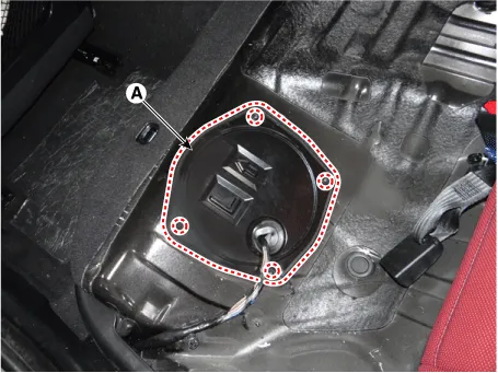
Remove the fuel pump service cover (A) after loosening the mounting screws.
|
| 5. |
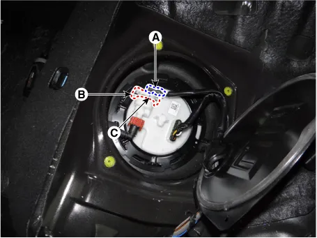
Disconnect the fuel feed quick-connector (A). |
| 6. |
Remove the fuel pressure sensor fixing pin (B). |
| 7. |
Remove the fuel pressure sensor from the fuel pump.
|
| Installation |
| 1. |
Install in the reverse order of removal. |


Other information:
Kia Stinger (CK) 2018-2023 Service Manual: Rear View Monitor (RVM)
Components and components location Component Location 1. Rear view monitor (RVM) 2. AVN Monitor 3. Steering angle sensor Description and operation Description 1. To display back of the vehicle to assist the driver, it receives vehicle rearside image signal from the rear view monitor and displays it on AVN monitor or LHS of inside rearview mirror.Repair procedures Operation and Leakage Check Check all of the following items: Component Procedure Brake Booster (A) Check brake operation by applying the brakes during a test drive. If the brakes do not work properly, check the brake booster. Replace the brake booster as an assembly if it does not work properly or if there are signs of leakage.Categories
- Manuals Home
- Kia Stinger Owners Manual
- Kia Stinger Service Manual
- New on site
- Most important about car
