Kia Stinger CK: Heater / Heater Unit
Components and components location
| Component Location |
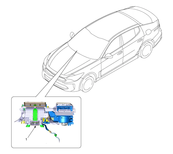
| 1. Heater Unit |
| Components |
| [LH] |
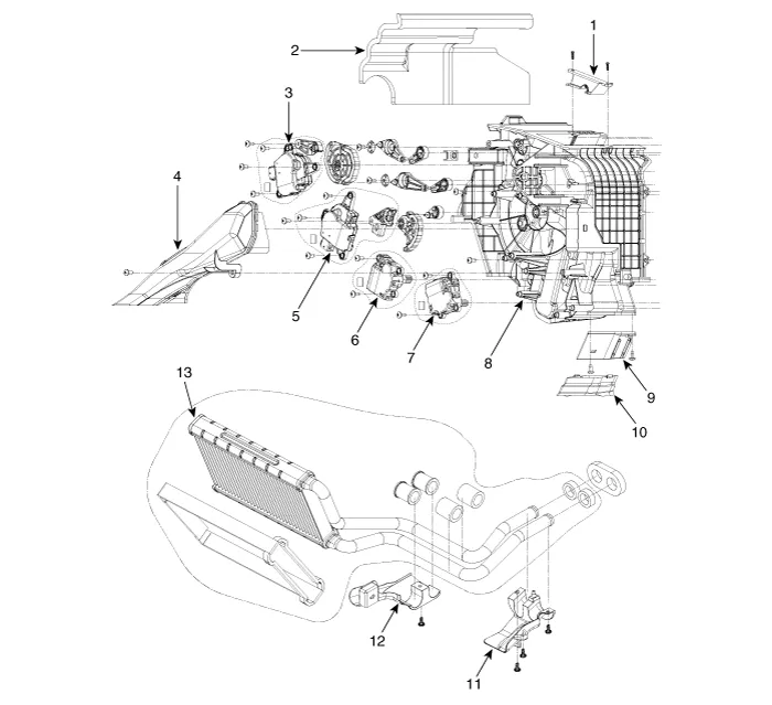
| 1. Air guard 2. Anti noise pad 3. Mode control actuator 4. Shower duct [LH] 5. Temperature control actuator 6. Console ON/OFF actuator 7. Console temperature control actuator |
8. Heater case [LH] 9. Rear heater duct 10. Rear heater duct 11. Heater core cover 12. Heater core cover 13. Heater core assembly |
| [RH] |
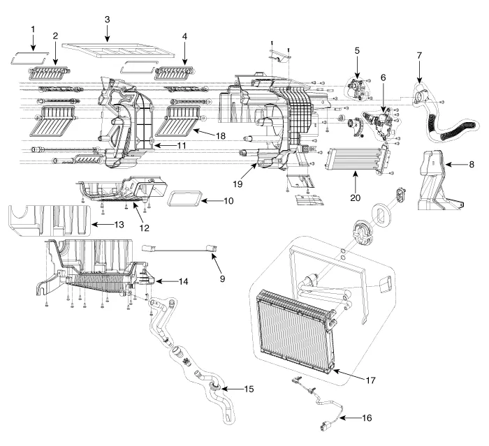
| 1. Deffog
seal 2. Auto defogging door [LH] 3. Seal 4. Auto defogging door [RH] 5. Auto defogging actuator 6. Temperature control actuator 7. Aspirator hose assembly 8. Shower duct [RH] 9. Evaporator insulation [Low] 10. Console seal |
11. Heater
seperator 12. Console cover 13. Anti noise pad 14. Heater case [Lower] 15. Drain hose 16. Evaporator temperature sensor 17. Evaporator core 18. Temperature control door 19. Heater case [RH] 20. PTC Heater |
Repair procedures
| Replacement |
| 1. |
Disconnect the negative (-) battery terminal. |
| 2. |
Recover the refrigerant with a recovery/recycling/charging station. |
| 3. |
When the engine is cool, drain the engine coolant from the radiator. D 2.2 R VGT (Refer to Engine Mechanical System - “Coolant”) G 2.0 T-GDI THETA (Refer to Engine Mechanical System - “Coolant”) G 3.3 T-GDI LAMBDA (Refer to Engine Mechanical System - “Coolant”) |
| 4. |
Remove the cowl top cover. (Refer to Body - "Cowl Top Cover") |
| 5. |
Remove the engine room partition. |
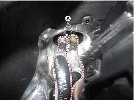
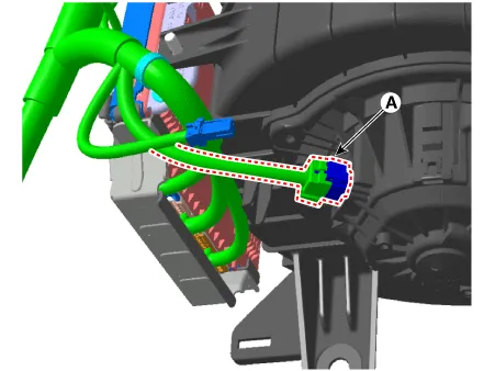
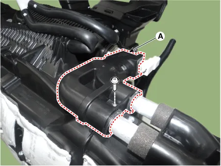
| 6. |
Remove the expansion valve (A) from the evaporator core after loosening the bolts.
|


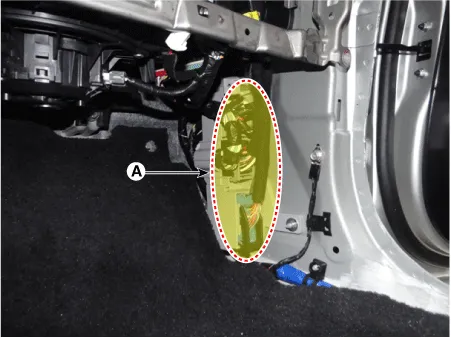
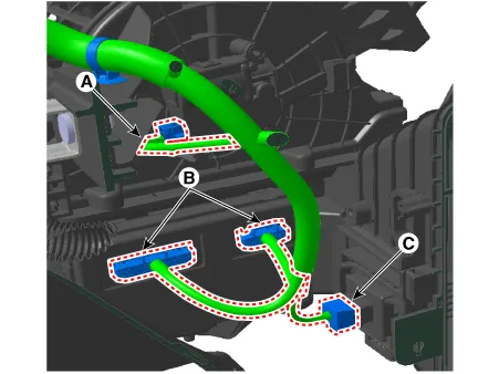
| 7. |
Disconnect the heater hoses (A).
|

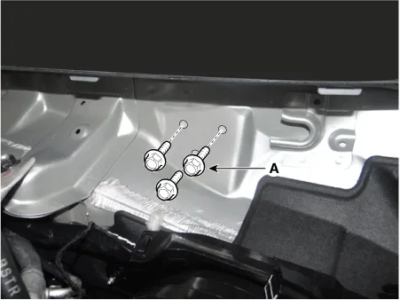
| 8. |
Loosen the cowl cross member mounting bolts (A).
|
| 9. |
Remove both sides of front seat assembly. (Refer to Body - "Front Seat Assembly") |
| 10. |
Remove the floor console. (Refer to Body - "Floor Console Assembly") |
| 11. |
Remove both sides of the front pillar trim. (Refer to Body - "Front Pillar Trim") |
| 12. |
Remove both sides of the cowl side trim. (Refer to Body - "Cowl Side Trim") |
| 13. |
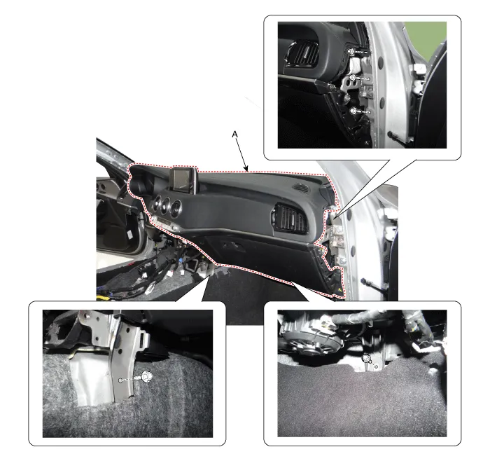
Remove the crash pad lower panel. (Refer to Body - "Crash Pad Lower Panel") |
| 14. |
Remove the steering column shroud lower panel. (Refer to Body - "Steering Column Shroud Panel") |
| 15. |
Remove the steering wheel. (Refer to Steering System - "Steering Wheel") |
| 16. |
Remove the multifunction switch. (Refer to Body Electrical System - "Multifunction Switch") |
| 17. |
Lower the steering column after loosening the mounting bolts. (Refer to Steering System - "Steering Column and Shaft") |
| 18. |
Remove the front door scuff trim. (Refer to Body - "Door Scuff Trim") |
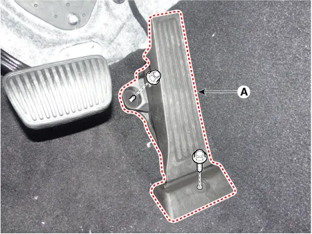
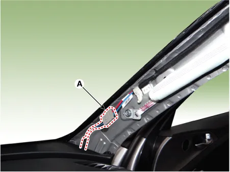
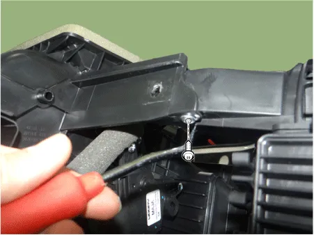
| 19. |
Separate the accelerator pedal (A) after loosening the bolts.
|
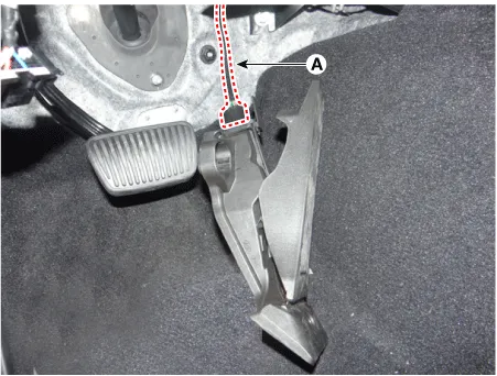
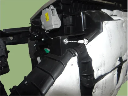
| 20. |
Remove the accelerator pedal after disconnecting the connector (A).
|
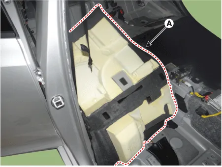
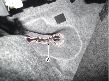
| 21. |
Separate the floor carpet (A) to allow space for removing the rear heating duct.
|
| 22. |
Remove the rear heating duct (A) after loosening the clip.
|

| 23. |
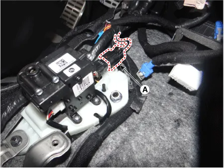
Disconnect the shift lever connector (A).
|
| 24. |
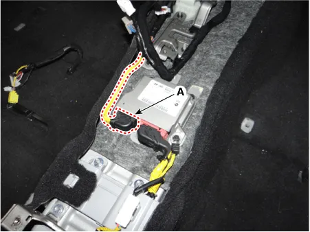
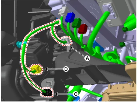
Disconnect the airbag control module (SRSCM) connector (A).
|
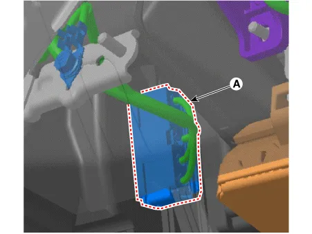
| 25. |
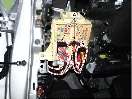
Disconnect the passenger compartment junction box connectors (A).
|
| 26. |
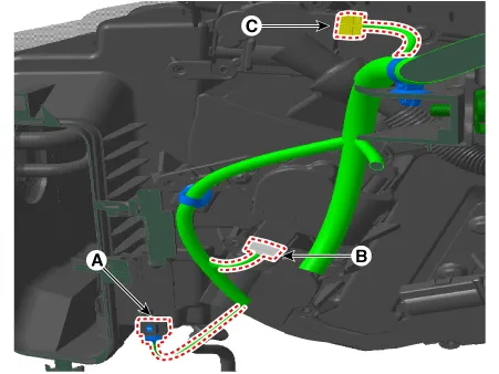
Disconnect the multi box connectors (A). [LH]
[RH]
|
| 27. |
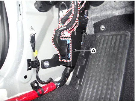
Disconnect the connector (A) and the mounting clips in the front pillar. [LH]
[RH]
|

| 28. |
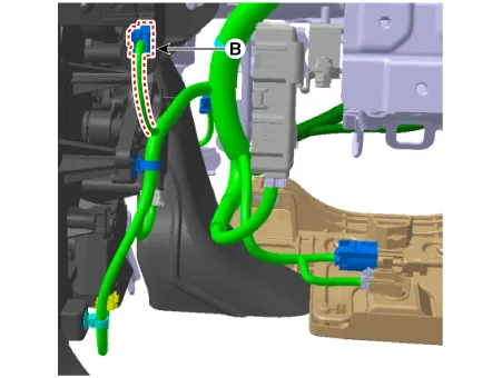
Remove the drain hose (A).
|
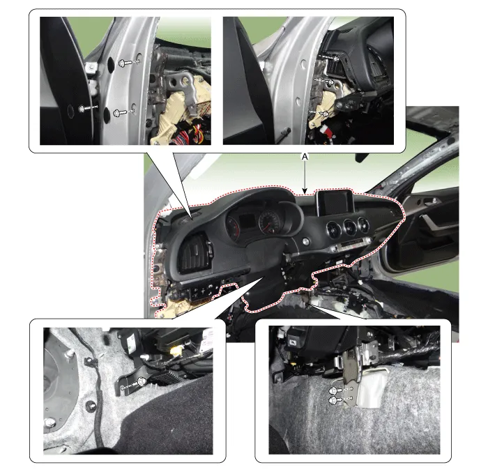
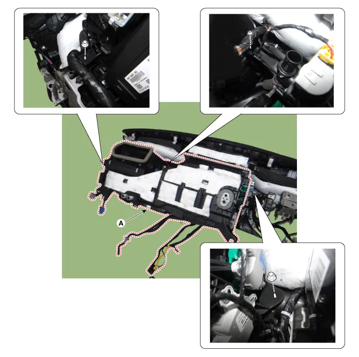
| 29. |
After loosening the nuts and bolts, remove the main crash pad and cowl cross bar assembly (A) altogether. [LH]
[RH]
|
| 30. |
Remove the integrated body control unit. (Refer to Body Electrical System - "Integrated Body Control Unit (IBU)") |
| 31. |
Disconnect the heater & blower unit connectors.
|
| 32. |
Remove the heater and blower unit (A) from the crash pad after loosening the mounting nuts.
|
| 33. |
Remove the heater core cover (A).
|

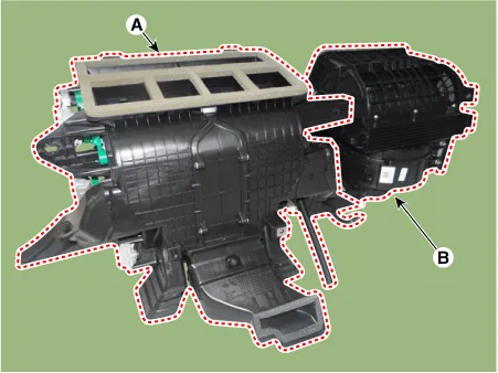
| 34. |
Separate the blower unit (B) from the heater unit (A) after loosening the screws.
|
| 35. |
Install in the reverse order of removal. |


Other information:
Kia Stinger (CK) 2018-2023 Service Manual: Front Seat Frame Assembly
Components and components location Component Location 1. Front seat back frame assembly 2. Front seat cushion frame assembly Repair procedures Replacement • Put on gloves to protect your hands.Components and components location Components 1. Front seat belt retractor 2. Rear seat belt retractor [RH] 3. Rear center seat belt retractor 4. Rear seat belt retractor[LH] 5.Rear seat belt buckle 6. Emergency fastening device (EFD) Front Seat Belt Retractor Components and components location Component Location 1.Categories
- Manuals Home
- Kia Stinger Owners Manual
- Kia Stinger Service Manual
- New on site
- Most important about car
