Kia Stinger CK: Hydraulic System / Oil Pump Unit (OPU)
Kia Stinger (CK) 2018-2023 Service Manual / Automatic Transmission System / Hydraulic System / Oil Pump Unit (OPU)
Components and components location
| Components Location |
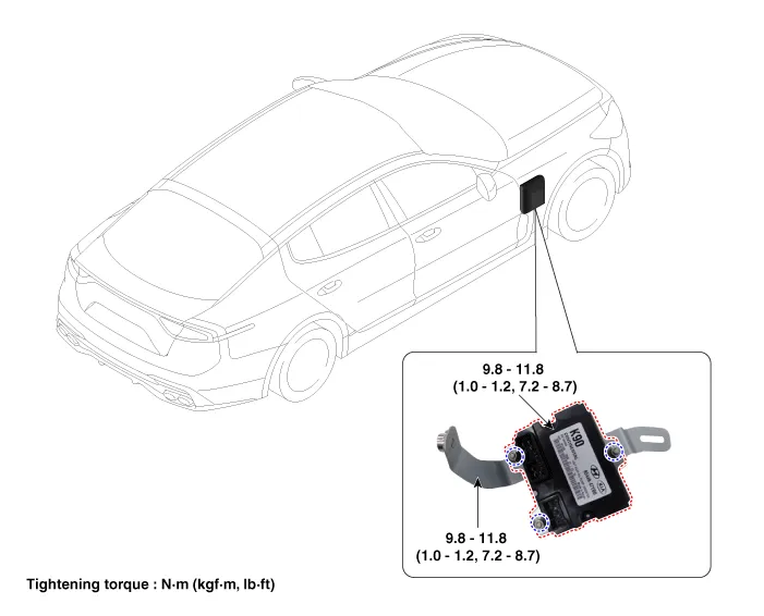
| 1. Oil Pump Unit (OPU) |
2. OPU bracket |
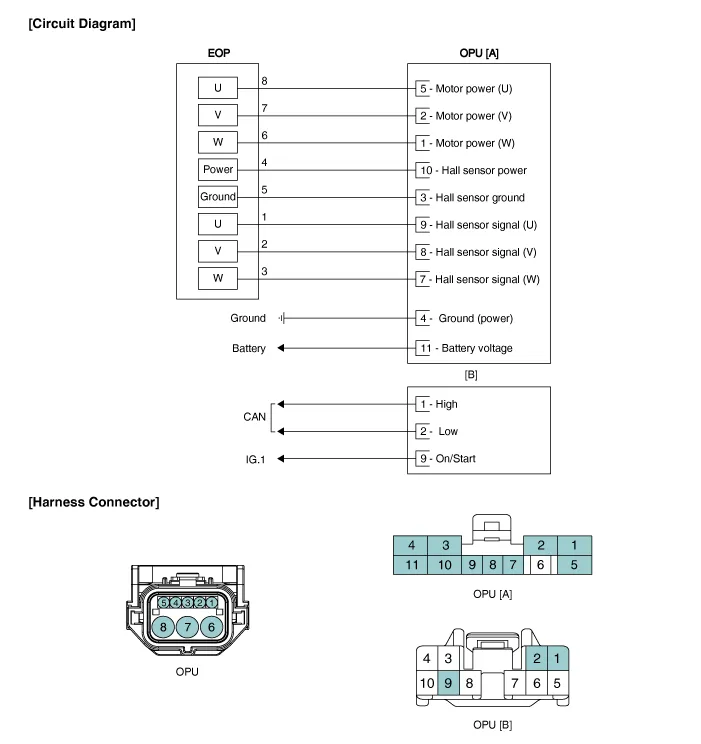
Schematic diagrams
| Circuit Diagram |
Repair procedures
| Removal |
| 1. |
Remove the integrated body control unit (IBU). (Refer to - Body Electrical System - "Integrated Body Control Unit") |
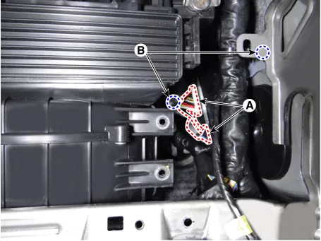
| 2. |
Disconnect the OPU connector (A) and then remove the OPU by loosening the OPU bracket nut (B).
|
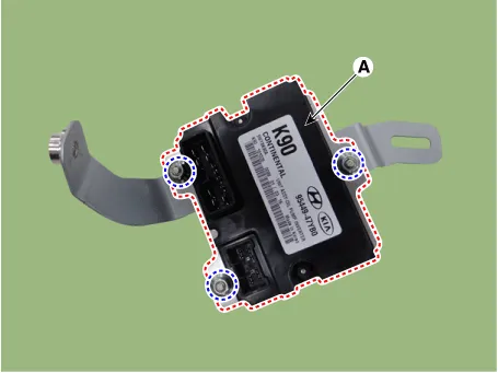
| 3. |
Remove the OPU (A) from the bracket.
|
| Installation |
| 1. |
Install in the reverse order of removal. |


Other information:
Repair procedures Front wheel alignment When using a commercially available computerized wheel alignment equipment to inspect the front wheel alignment, always position the vehicle on a level surface with the front wheels facing straight ahead. Prior to inspection, make sure that the front suspension and steering system are in normal operating condition and that the tires are inflated to the specified pressure.Service data Service data Item Specification Master cylinder Type Tandem Cylinder I.D. Ø 23.81 mm (0.937 in) Piston stroke 36±1 mm (1.41 ± 0.039 in) Fluid level switch Provided Brake booster Type 8+8" Tandem Boosting ratio 9 : 1 Front disc brake (17 in) Type Ventilated disc Disc O.Categories
- Manuals Home
- Kia Stinger Owners Manual
- Kia Stinger Service Manual
- New on site
- Most important about car

Copyright © 2026 www.kstinger.com 0.0137