Kia Stinger CK: Hydraulic System / R Position Solenoid Valve (ON/OFF)
Specifications
| Specifications |
|
Item |
Specification |
|
Control type |
ON/OFF |
|
Control pressure kpa (kgf/cm², psi) |
539.36 (5.5, 78.23) |
|
Current (mA) |
0 - 600 |
|
Coil resistance (Ω) |
10.5 ± 0.5 |
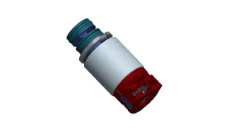
Components and components location
| Components Location |

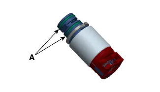
| 1. R position solenoid valve
|
2. Solenoid valve support bracket
|
Description and operation
| Description |
| • |
R position solenoid valve is ON/OFF type. |
| • |
When TCM supplies current to solenoid valve, the solenoid valve operates and controls the R range. |
Solenoid Valve Operation Table
|
|
ON/OFF |
|
(R) |
|
|
P |
|
|
N |
|
|
1 |
|
|
2 |
|
|
3 |
|
|
4 |
|
|
5 |
|
|
6 |
|
|
7 |
|
|
8 |
|
|
REV |
● |
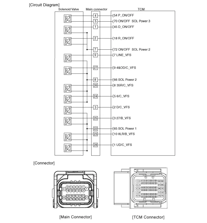
Schematic diagrams
| Circuit Diagram |
Repair procedures
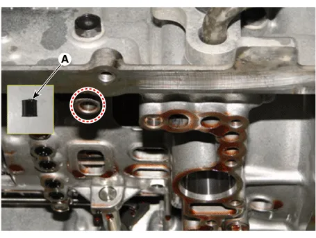
| Inspection |
| 1. |
Switch "OFF" ignition |
| 2. |
Disconnect the main connector (A).
|

| 3. |
Measure the resistance between power terminal (7) and signal terminal (2).
|
| Removal |
|

| 1. |
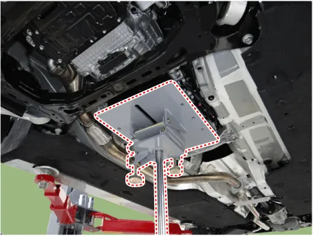
Remove the under cover. (Refer to Engine Mechanical System - "Engine Room Under Cover"). |
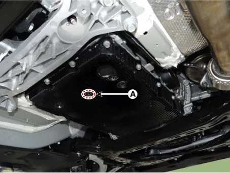
| 2. |
Remove the ATF drain plug (A), allow the fluid to drain out and then reinstall the drain plug.
|

| 3. |
Disconnect the main connector (A).
|
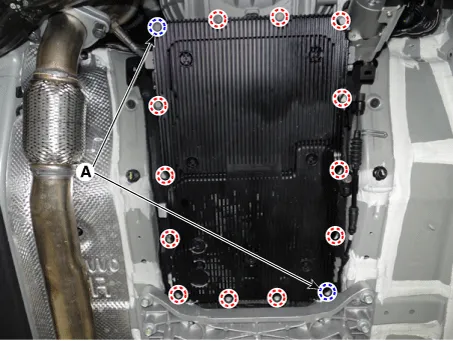
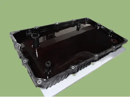
| 4. |
Remove the valve body cover.
|
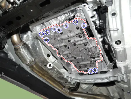
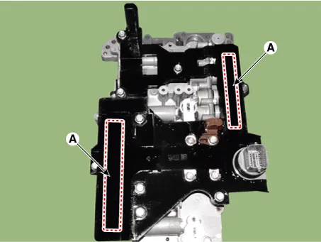
| 5. |
Remove the valve body assembly (A) after loosening the bolts.
|
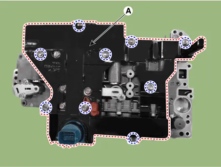
| 6. |
Remove the E-module (A) after loosening the bolts.
|
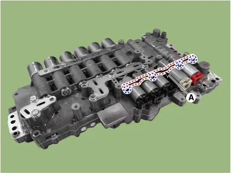
| 7. |
Remove the solenoid valve support bracket (A).
|
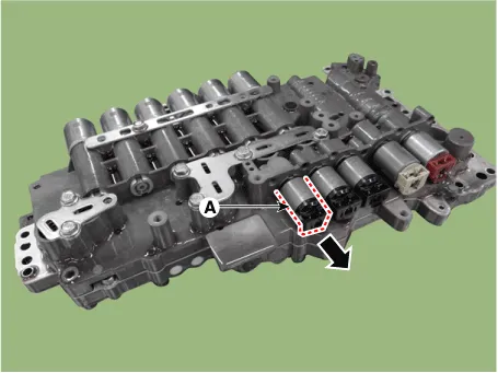
| 8. |
Remove the R position solenoid valve (A).
|
| Installation |
| 1. |
Install in the reverse order of removal.
|
| 2. |
Perform the procedures below after installing.
|


Other information:
Kia Stinger (CK) 2018-2023 Service Manual: Inside Rear View Mirror
Components and components location Component Location 1. Inside rear view mirror Repair procedures Replacement Put on gloves to protect your hands. • Use a plastic panel removal tool to remove interior trim pieces without marring the surface.Kia Stinger (CK) 2018-2023 Service Manual: Lower Anchors and Tether for Children (LATCH) System
The LATCH system holds a child restraint during driving and in an accident. This system is designed to make installation of the child restraint easier and reduce the possibility of improperly installing your child restraint. The LATCH system uses anchors in the vehicle and attachments on the child restraint. The LATCH system eliminates the need to use seat belts to secure the child restraint to the rear seats.Categories
- Manuals Home
- Kia Stinger Owners Manual
- Kia Stinger Service Manual
- New on site
- Most important about car
