Kia Stinger CK: Hydraulic System / UD Clutch Control Soleoind Valve (UD/C_VFS)
Specifications
| Specifications |
|
Item |
Specification |
|
Control type |
N/L (Normal Low) |
|
Control pressure kpa (kgf/cm², psi) |
0 - 1,569.06 (0 - 16, 0 - 227.57) |
|
Current (mA) |
0 - 1,100 |
|
Coil resistance (Ω) |
5.3 ± 0.3 |
Components and components location
| Components Location |

| 1. UD clutch control solenoid
valve |
2. Solenoid valve support bracket
|
Description and operation
| Description |
| • |
UD clutch control solenoid valve is a Variable Force Solenoid (VFS) type. |
| • |
When TCM supplies variable current to solenoid valve, hydraulic pressure of 4&OD clutch is controlled directly by solenoid valve. |

Solenoid Valve Operation Table
|
|
Solenoid Valve |
Clutch |
|
UD/C_VFS |
UD/C |
|
|
P |
|
|
|
N |
|
|
|
1 |
● |
● |
|
2 |
● |
● |
|
3 |
● |
● |
|
4 |
● |
● |
|
5 |
|
|
|
6 |
|
|
|
7 |
|
|
|
8 |
|
|
|
REV |
|
|
Schematic diagrams
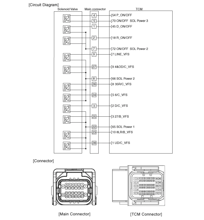
| Circuit Diagram |
Repair procedures
| Inspection |
| 1. |
Switch "OFF" ignition |
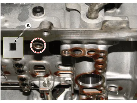
| 2. |
Disconnect the main connector (A).
|

| 3. |
Measure the resistance between power terminal (22) and signal terminal (28).
|
| Removal |
|

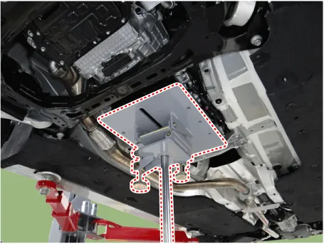
| 1. |
Remove the under cover. (Refer to Engine Mechanical System - "Engine Room Under Cover"). |
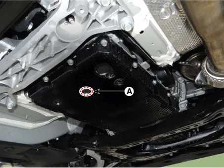
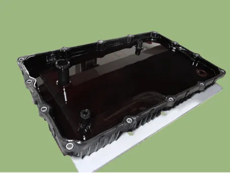
| 2. |
Remove the ATF drain plug (A), allow the fluid to drain out and then reinstall the drain plug.
|

| 3. |
Disconnect the main connector (A).
|
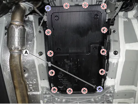
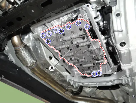
| 4. |
Remove the valve body cover.
|
| 5. |
Remove the valve body assembly (A) after loosening the bolts.
|
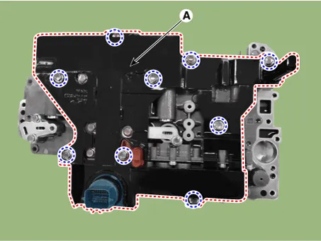
| 6. |
Remove the E-module (A) after loosening the bolts.
|
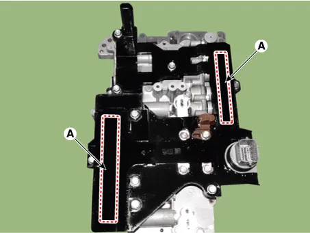
| 7. |
Remove the solenoid valve support bracket (A).
|
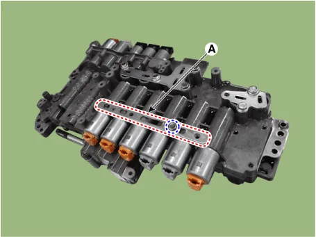
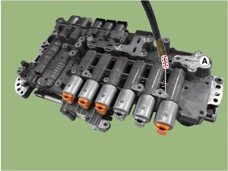
| 8. |
Remove the pin (A).
|
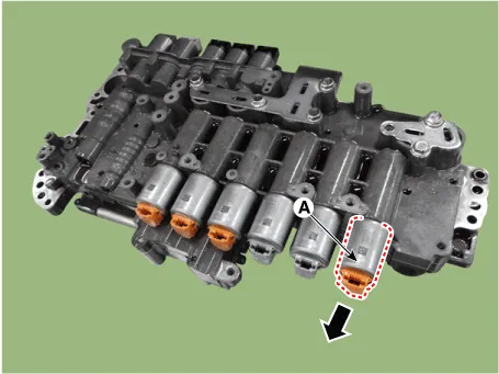
| 9. |
Remove the UD clutch control solenoid valve (A).
|
| Installation |
| 1. |
Install in the reverse order of removal.
|
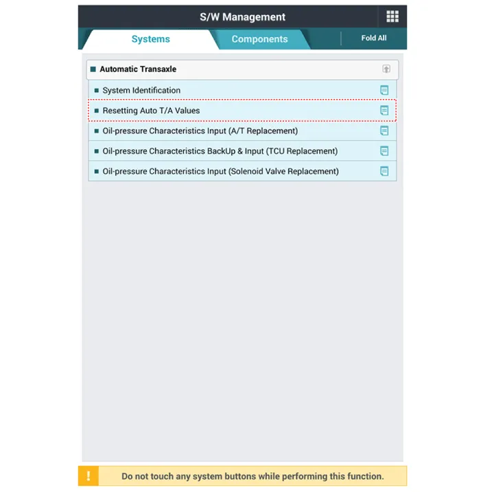
| 2. |
Perform the procedures below after installing.
|


Other information:
Kia Stinger (CK) 2018-2023 Service Manual: For best battery service
Keep the battery securely mounted. Keep the battery top clean and dry. Keep the terminals and connections clean, tight, and coated with petroleum jelly or terminal grease. Rinse any spilled electrolyte from the battery immediately with a solution of water and baking soda. If the vehicle is not going to be used for an extended time, disconnect the battery cables.Repair procedures Replacement Put on gloves to protect your hands. • Use a plastic panel removal tool to remove interior trim pieces without marring the surface.Categories
- Manuals Home
- Kia Stinger Owners Manual
- Kia Stinger Service Manual
- New on site
- Most important about car
