Kia Stinger CK: Hydraulic System / Line Pressure Control Solenoid Valve (LINE_VFS)
Specifications
| Specifications |
|
Item |
Specification |
|
Control type |
N/L (Normal Low) |
|
Control pressure kpa (kgf/cm², psi) |
0 - 519.75 (0 - 5.3, 0 - 75.38) |
|
Current (mA) |
0 - 850 |
|
Coil resistance (Ω) |
5.1 ± 0.3 |
Components and components location
| Components Location |
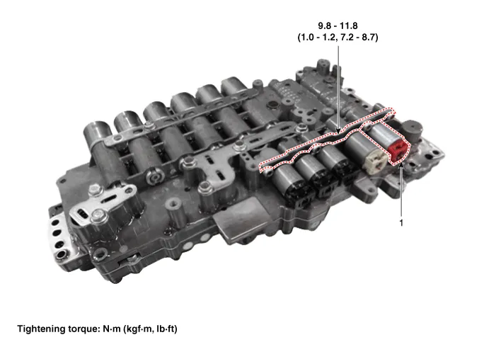
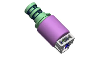
| 1. Line pressure control solenoid
valve |
2. Solenoid valve support bracket
|
Description and operation
| Description |
| • |
Line pressure solenoid valve is a Variable Force Solenoid (VFS) type. |
| • |
When TCM supplies variable current to solenoid valve, hydraulic pressure is controlled indirectly by solenoid valve. |
Schematic diagrams
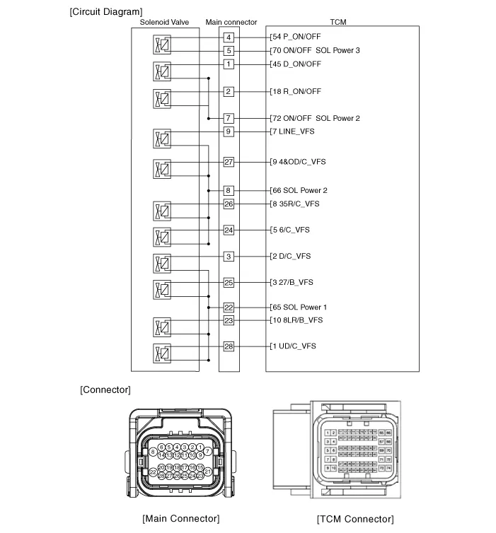
| Circuit Diagram |
Repair procedures
| Inspection |
| 1. |
Switch "OFF" ignition |
| 2. |
Disconnect the main connector (A).
|

| 3. |
Measure the resistance between power terminal (8) and signal terminal (9).
|
| Removal |
|

| 1. |
Remove the under cover. (Refer to Engine Mechanical System - "Engine Room Under Cover"). |
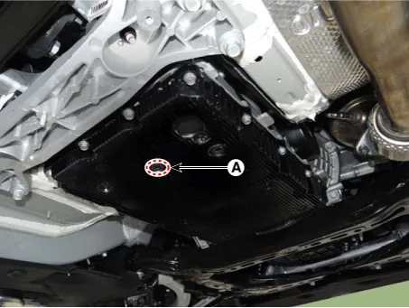
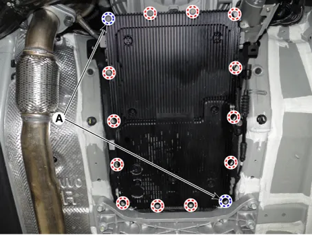
| 2. |
Remove the ATF drain plug (A), allow the fluid to drain out and then reinstall the drain plug.
|

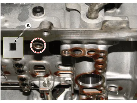
| 3. |
Disconnect the main connector (A).
|
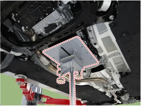
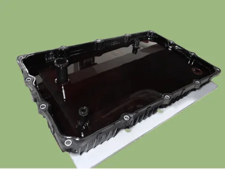
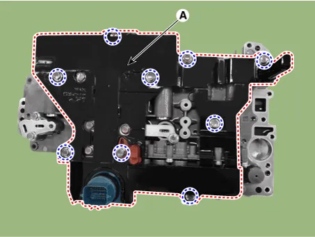
| 4. |
Remove the valve body cover.
|
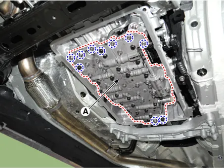
| 5. |
Remove the valve body assembly (A) after loosening the bolts.
|
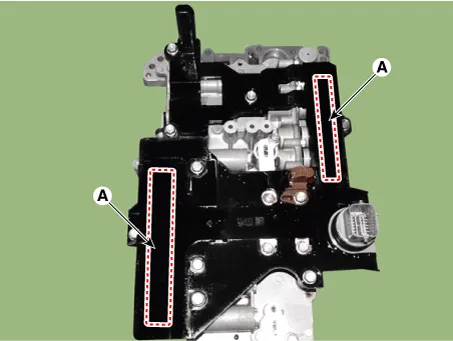
| 6. |
Remove the E-module (A) after loosening the bolts.
|
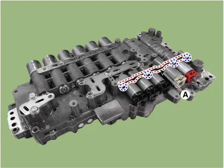
| 7. |
Remove the solenoid valve support bracket (A).
|
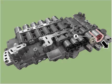
| 8. |
Remove the line pressure control solenoid valve (A).
|
| Installation |
| 1. |
Install in the reverse order of removal.
|
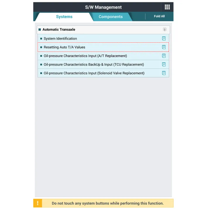
| 2. |
Perform the procedures below after installing.
|


Other information:
Kia Stinger (CK) 2018-2023 Service Manual: Indicators And Gauges
Components and components location Components Standard Type ("3.5" inch) Super Vision Type ("7" inch) Connector Pin Information No. Description No. Description 1 Ground (Signal3) 21 Trip switch (-) 2 Illumination (-) 22 Trip switch 1 (+) 3 Description and operation Description Via the seat belt/door switch, the ISG function can detect if the driver side seat belt is fastened and the driver side door is closed. If the driver side seat belt/door are not fastened/closed, the ISG system will not operate. If the seat belt/door are unfastened/opened, the engine will not start or stop by the ISG function for safety reasons.Categories
- Manuals Home
- Kia Stinger Owners Manual
- Kia Stinger Service Manual
- New on site
- Most important about car
