Kia Stinger CK: 4 Wheel Drive (AWD) System / AWD Control System
Components and components location
| Components Location |
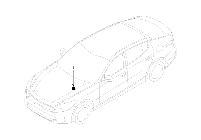
| 1. AWD
ECU |
Description and operation
| Description |
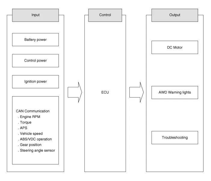
The AWD ECU distributes the driving force to the front/rear wheel through controlling the multi plate clutch on the AWD transfer case by analyzing the input information, i.e. the wheel speed, accelerator and steering angle depending on the road condition and driving state. The AWD vehicle has different power transmitting conditions depending on the driving/road conditions. The vehicle speed is transmitted through CAN communication from ABS/ESP ECU. The information from the CAN communication includes the APS which indicates the driver’s intention of acceleration, engine torque, ABS/ESP operation signal and gear position. The AWD ECU controls the DC motor, warning lamp and indicating lamp and communicates with the tester equipment. When a vehicle runs at normal speed higher than 60KPH on regular roads, it is controlled under the 2WD conditions. The ECU decides the driving force on the front and rear wheel by receiving the signals from all sensors depending on the driving conditions, i.e. abrupt starting, turning and driving on the low friction road, and the optimized torque which is proper to the driving condition is transmitted to the front wheel through calculating and controlling the transmitted torque data.
Flow diagram
| AWD ECU input/output diagram |
Schematic diagrams
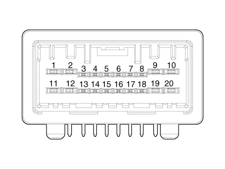
| AWD ECU terminal function |
| [AWD ECU connector] |
|
Pin |
Description |
|
1 |
Motor B |
|
2 |
Motor A |
|
5 |
Pressure sensor suplly |
|
7 |
IG1 |
|
8 |
Motor shield wire ground |
|
9 |
Beterry ground |
|
10 |
Beterry |
|
14 |
Pressure sensor signal |
|
15 |
Pressure sensor ground |
|
17 |
CAN HIGH |
|
18 |
CAN LOW |
Repair procedures
| Removal |
| 1. |
Turn ignition switch OFF and disconnect the negative (-) battery cable. |
| 2. |
Remove the crash pad lower panel. (Refer to Body - "Crash Pad Lower Panel") |
| 3. |
Remove the knee airbag. (Refer to Restraint - "Knee Airbag (KAB) Module") |
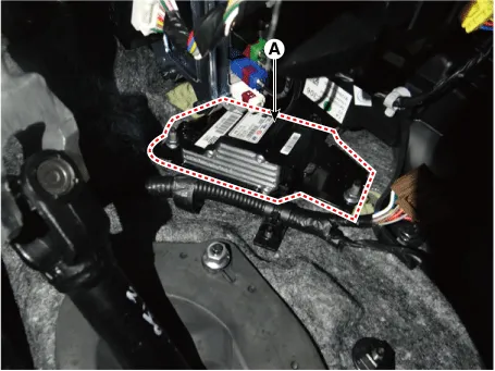
| 4. |
Disconnect the AWD ECU connector (A).
|
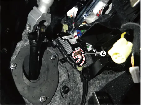
| 5. |
Loosen the AWD ECU bracket nuts and then remove the AWD ECU (A).
|
| Installation |
| 1. |
Install in the reverse order of removal. |
Prior to installing a new ECU, upload the original ECU's clutch learning to the new ECU using the KDS tool. (Refer to 4 Wheel Drive (AWD) System - "Repair procedures") |


Other information:
Kia Stinger (CK) 2018-2023 Service Manual: Manifold Absolute Pressure Sensor (MAPS)
Specifications Specification Item Specification Output Voltage (V) 5 Pressure (KPa) 32.5 - 284 Operating Voltage (V) 4.5 - 5.5 Pressure [kPa (kgf/cm², psi)] Output Voltage (Vref = 5V) 32.Kia Stinger (CK) 2018-2023 Service Manual: Power Window Switch
Components and components location Components Driver Power Window Switch Assist Power Window Switch Rear Power Window Switch Schematic diagrams Circuit Diagram Driver Power Window Switch [Front Safety + IMS Type] [Front Safety + Non-IMS Type] Assist Power Window Switch [Door Lock Type] [Non-Door Lock Type] Rear Power Window Switch [Seat Warmer Type] [Non-Seat Warmer Type] Repair procedures Inspection Diagnosis With KDS 1.Categories
- Manuals Home
- Kia Stinger Owners Manual
- Kia Stinger Service Manual
- New on site
- Most important about car
