Kia Stinger CK: Automatic Transmission Control System / Parking Switch
Specifications
| Specifications |
Specifications
|
Item |
Specification |
|
Output type |
PWM (S1, S2), ON/OFF (Ps, Ns) |
|
Power supply (V) |
5 (S1, S2), 12 (Ps, Ns) |
Signal code table
|
Signal |
P |
Not P |
|
S1 |
5 V |
0 |
|
S2 |
0 |
5 V |
|
Ps |
12 V |
0 |
|
Ns |
0 |
12 V |
Components and components location
| Components Location |
| 1. Parking switch |
2. Parking release lever |
Description and operation
| Description |
The system determines whether parking is active in the TCM by whether the S1 (P) pin and S2 (Not P) pin are ON or OFF, based on the working angle.

Schematic diagrams
| Circuit Diagram |

Repair procedures
| Inspection |
Inspect the connector thoroughly for looseness, poor connection, bending, corrosion, contamination, deformation, or damage. |

| 1. |
Disconnect the parking switch connector. |
| 2. |
Turn Ignition "ON", & engine "OFF". |
| 3. |
Measure the each signal in "P" range or "not p" range. Signal code table
Connection table
|
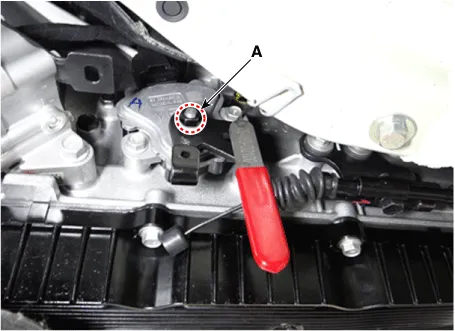
| Removal |
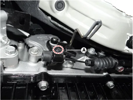
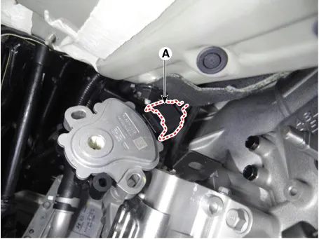
| 1. |
Remove the parking release cable after loosening the fastener (A).
|
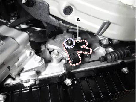
| 2. |
Remove the parking release lever (A) after loosening the nut.
|
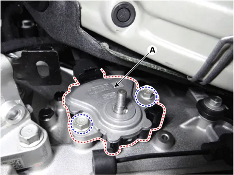
| 3. |
Remove the parking switch (A) after loosening the bolts.
|
| 4. |
Disconnect the parking switch connector (A).
|
| Installation |
| 1. |
Connect the parking switch connector (A).
|
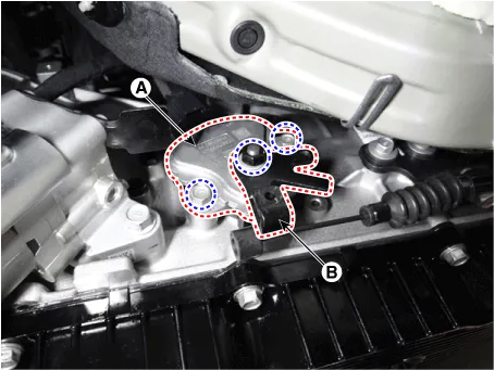
| 2. |
Install the parking switch (A) and parking release lever (B).
|

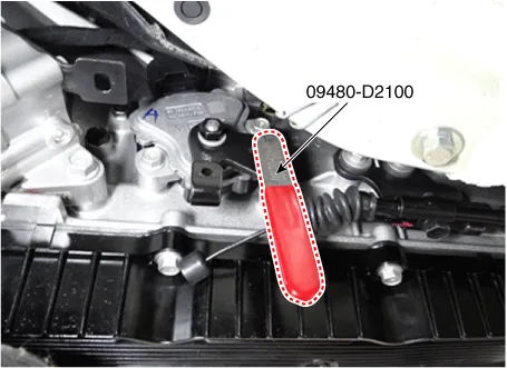
| 3. |
Align the hole in the parking release lever with the "P" position hole of the parking switch and then insert the SST parking switch guide pin (09480-D2100).
|
| 4. |
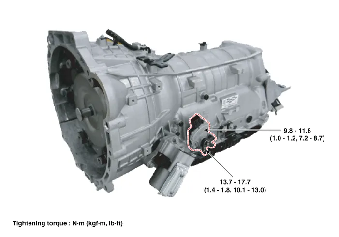
Tighten the parking switch mounting bolts (A).
|
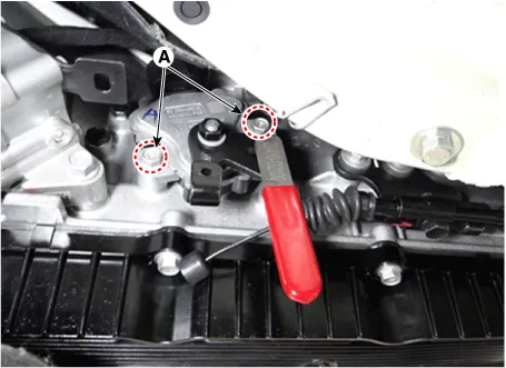
| 5. |
Tighten the parking release lever mounting nut (A).
|
| 6. |
Remove ths SST (09480-D2100)
|
| 7. |
Tighten the fastener (A) after installing the parking release cable.
|


Other information:
Kia Stinger (CK) 2018-2023 Service Manual: General Service Information
General information Identification Number Locations Protection of the Vehicle Always be sure to cover fenders, seats, and floor areas before servicing. Insert the supportive rod into the hole at the edge of the hood whenever inspecting the engine compartment to prevent the hood from falling and causing possible injury.Kia Stinger (CK) 2018-2023 Service Manual: Floor Console Assembly
Components and components location Component Location 1. Floor console assembly Repair procedures Replacement Put on gloves to protect your hands. • Use a plastic panel removal tool to remove interior trim pieces without marring the surface.Categories
- Manuals Home
- Kia Stinger Owners Manual
- Kia Stinger Service Manual
- New on site
- Most important about car
