Kia Stinger CK: Automatic Transmission Control System / Speed Sensor
Specifications
| Specifications |
|
Item |
Specification |
|
Type |
Hall effect sensor |
|
Operating condition (°C)°F |
(-40 to 150)-40 to 302 |
|
Output voltage (V) |
High :1.4 |
|
Low : 0.7 |
Components and components location
| Components |
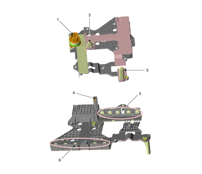
| 1. E module connector 2. Output speed sensor 3. Input speed sensor |
4. Oil temperature sensor 5. Indirect control solenoid valve connector 6. Direct control solenoid valve connector |
Description and operation
| Description |
| • |
Speed sensor is integrated with E module. |
| • |
Speed sensor uses an electric current type hall sensor in which the current is changed |
| • |
The speed sensor measures the rate of rotation of the input & output shafts inside the transmission and delivers the readings to the TCM. |
| • |
The sensor provides critical input data used in feedback control, torque converter clutch control, gear setting control, line pressure control, clutch activation pressure control, and sensor fault analysis. |
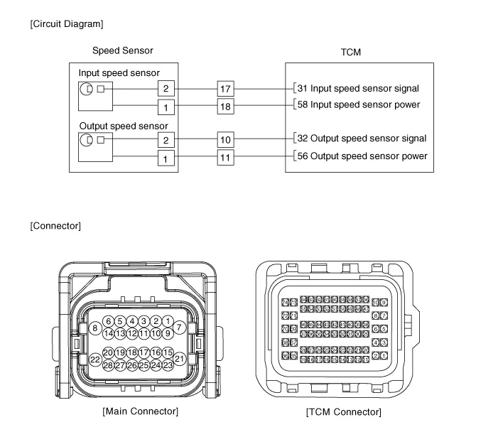
Schematic diagrams
| Circuit Diagram |
Repair procedures
| Inspection |
| 1. |
Check signal waveform of speed sensor using the KDS. |
| Replacement |
The speed sensor is integrated into the E-module that can’t be disassembled. So refer to “E-module” for the removal or installation procedure of the speed sensor. |

| 1. |
Replace the E-module. (Refer to Automatic Transmission Control System - "E-Module") |


Other information:
Kia Stinger (CK) 2018-2023 Service Manual: DC/DC Converter
Components and components location Components Location Schematic diagrams Circuit Diagram [200W] [400W] Terminal Function [200W] PIn. Description PIn. Description 1 Battery power (B+) input 7 ISG signal input 2 - 8 ACC input 3 - 9 ACC output 4 Battery power (B+) output 10 Ground 5 - 11 - 6 IGN1 input [400W] PIn.Kia Stinger (CK) 2018-2023 Service Manual: Lower Anchors and Tether for Children (LATCH) System
The LATCH system holds a child restraint during driving and in an accident. This system is designed to make installation of the child restraint easier and reduce the possibility of improperly installing your child restraint. The LATCH system uses anchors in the vehicle and attachments on the child restraint. The LATCH system eliminates the need to use seat belts to secure the child restraint to the rear seats.Categories
- Manuals Home
- Kia Stinger Owners Manual
- Kia Stinger Service Manual
- New on site
- Most important about car
