
Kia Stinger CK: Automatic Transmission Control System / Inhibitor Switch
Specifications
| Specifications |
|
Item |
Specification |
|
Output type |
PWM |
|
Power supply (V) |
5 |
Components and components location
| Components Location |
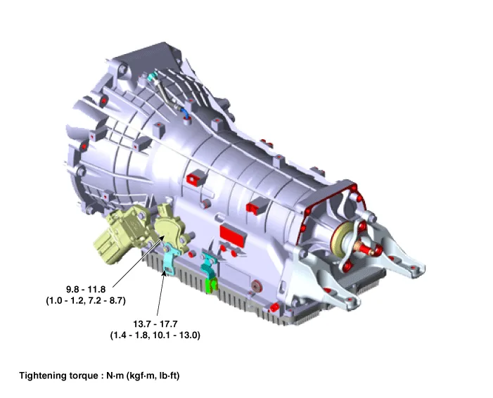
| 1. Inhibitor switch |
2. Manual control lever |
Schematic diagrams
| Circuit Diagram |

Repair procedures
| Inspection |
Inspect the connector thoroughly for looseness, poor connection, bending, corrosion, contamination, deformation, or damage. |

| 1. |
Disconnect the parking switch connector. |
| 2. |
Turn Ignition "ON", & engine "OFF". |
| 3. |
Measure the output signal in each range (P, R, N, D). Signal code table
Connection table
|
| Removal |
| 1. |
Shift the gear to "N". |
| 2. |
Disconnect the negative (-) battery terminal. |
| 3. |
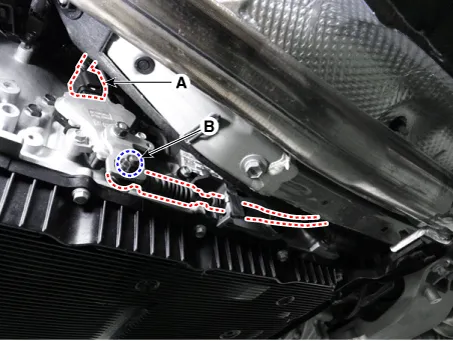
Inhibitor switch connector (A) and loosen the nut (B).
|
| 4. |
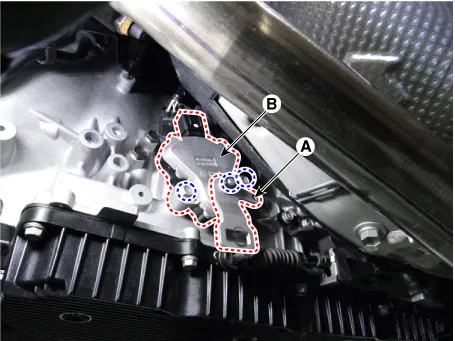
Remove the manual control lever (A) and then remove the inhibitor switch (B).
|
| Installation |
| 1. |
Install the inhibitor switch (B) and manual control lever (A).
|

| 2. |
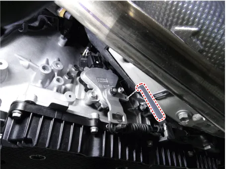
Install the SST (09480-D2100).
|
| 3. |
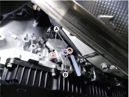
Tighten the inhibitor switch mounting bolts (A) and manual control lever mounting nut (B).
|
| 4. |
Remove the SST (09480-D2100). |
| 5. |
Connect the inhibitor switch connector (A) and tighten shift cable mounting nut (B).
|


Other information:
Kia Stinger (CK) 2018-2023 Service Manual: Rear Disc Brake
Components and components location Components [Standard] 1. Caliper housing 2. Brake member 3. Brake pad assembly [IN] 4. Retainer 5. Brake pad assembly [OUT] 6. Brake pad return spring [Brembo] 1. Caliper housing 2. Brake pad 3. Brake pad 4.Kia Stinger (CK) 2018-2023 Service Manual: Blind-Spot Collision Warning (BCW) Unit
Components and components location Components Repair procedures Removal lf replacement of the bracket or extension wire of BCW unit is required, it is recommended to surely replace the defective part only with a new one, not the whole BCW unit.Categories
- Manuals Home
- Kia Stinger Owners Manual
- Kia Stinger Service Manual
- New on site
- Most important about car
