Kia Stinger CK: Hydraulic System / Electronic Oil Pump (EOP)
Kia Stinger (CK) 2018-2023 Service Manual / Automatic Transmission System / Hydraulic System / Electronic Oil Pump (EOP)
Components and components location
| Components Location |
| 1. Electric Oil Pump (EOP)
|
Schematic diagrams
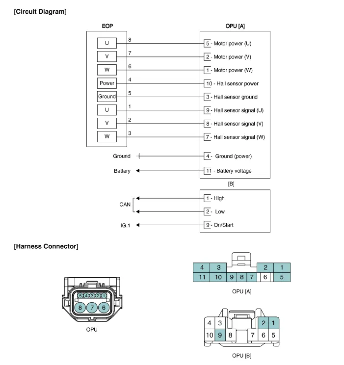
| Circuit Diagram |
Repair procedures
| Removal |
| 1. |
Remove the under cover. (Refer to Engine Mechanical System - "Engine Room Under Cover") |
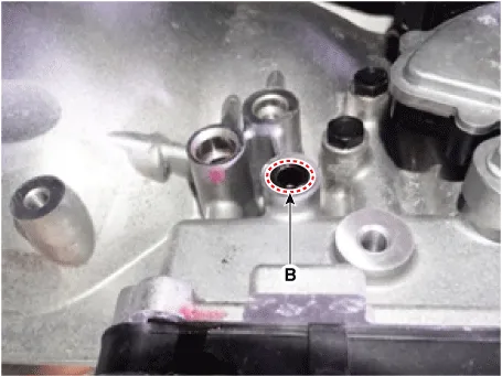
| 2. |
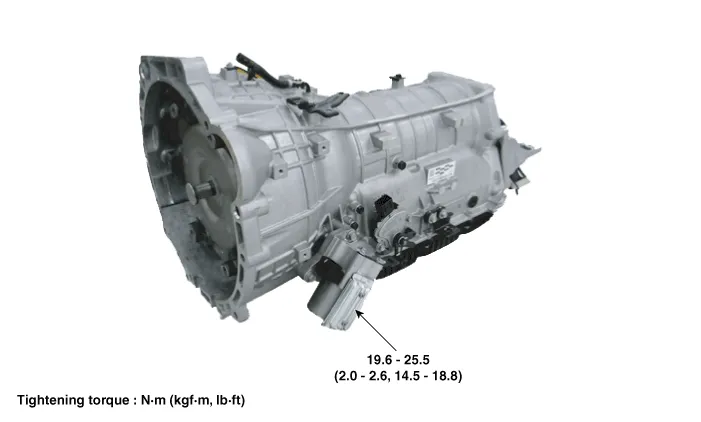
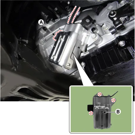
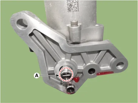
Disconnect the EOP connector (A) and remove the EOP (B) by loosening the bolts.
|
| Installation |
| 1. |
Install in the reverse order of removal.
|

| 2. |
Refill the automatic transmission with fluid. (Refer to Hydraulic System - "Fluid") |


Other information:
Kia Stinger (CK) 2018-2023 Service Manual: Knee Airbag (KAB) Module
Description and operation Description Installed inside the crash pad, the knee airbag (KAB) protects the driver in the event of a frontal crash. The SRSCM determines if and when to deploy the KAB. Never attempt to measure the circuit resistance of the airbag module (squib) even if you are using a specified tester.Kia Stinger (CK) 2018-2023 Service Manual: Exhaust Gas Temperature Sensor (EGTS)
Specifications Specification Exhaust Gas Temperature Sensor (EGTS) #1, 2 ▷ Type : Thermistor type Temperature [°C (°F)] Resistance (kΩ) -40 (-40) 0.17 0 (-32) 0.201 100 (212) 0.276 200 (392) 0.Categories
- Manuals Home
- Kia Stinger Owners Manual
- Kia Stinger Service Manual
- New on site
- Most important about car

Copyright © 2026 www.kstinger.com 0.0138