Kia Stinger CK: Hydraulic System / 4&OD Clutch Control Solenoid Valve (4&OD/C_VFS)
Specifications
| Specifications |
|
Item |
Specification |
|
Control type |
N/H (Normal High) |
|
Control pressure kpa (kgf/cm², psi) |
0 - 1,569.06 (0 - 16, 0 - 227.57) |
|
Current (mA) |
0 - 1,100 |
|
Coil resistance (Ω) |
5.3 ± 0.3 |
Components and components location
| Components Location |
| 1. 4&OD clutch control solenoid
valve |
2. Solenoid valve support bracket
|
Description and operation
| Description |
| • |
4&OD clutch control solenoid valve is a Variable Force Solenoid (VFS) type. |
| • |
When TCM supplies variable current to solenoid valve, hydraulic pressure of 4&OD clutch is controlled directly by solenoid valve. |

Solenoid Valve Operation Table
|
|
Solenoid Valve |
Clutch |
|
4&OD/C_VFS |
4&OD/C |
|
|
P |
● |
|
|
N |
● |
|
|
1 |
● |
|
|
2 |
● |
|
|
3 |
● |
|
|
4 |
|
● |
|
5 |
|
● |
|
6 |
|
● |
|
7 |
|
● |
|
8 |
|
● |
|
REV |
● |
|
Schematic diagrams
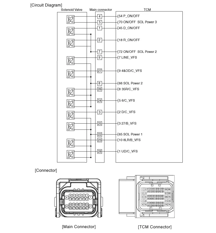
| Circuit Diagram |
Repair procedures
| Inspection |
| 1. |
Switch "OFF" ignition |
| 2. |
Disconnect the main connector (A).
|

| 3. |
Measure the resistance between power terminal (8) and signal terminal (27).
|
| Removal |
|

| 1. |
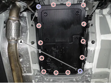
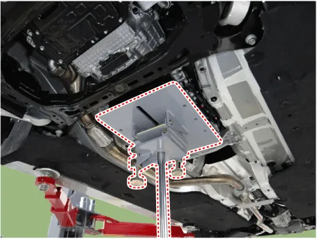
Remove the under cover. (Refer to Engine Mechanical System - "Engine Room Under Cover"). |
| 2. |
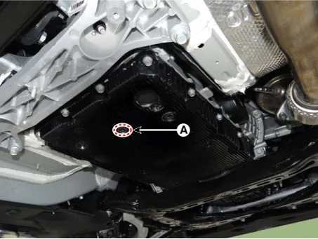
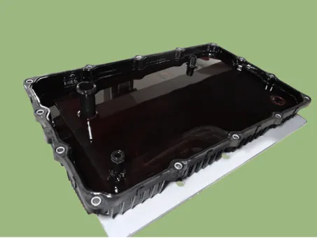
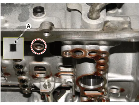
Remove the ATF drain plug (A), allow the fluid to drain out and then reinstall the drain plug.
|

| 3. |
Disconnect the main connector (A).
|
| 4. |
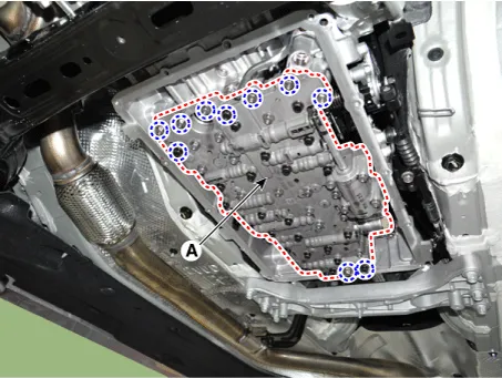
Remove the valve body cover.
|
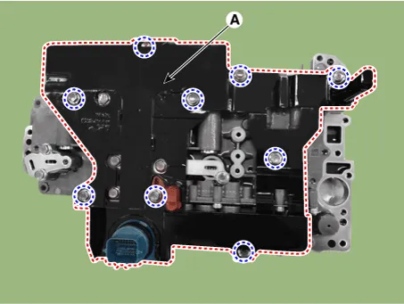
| 5. |
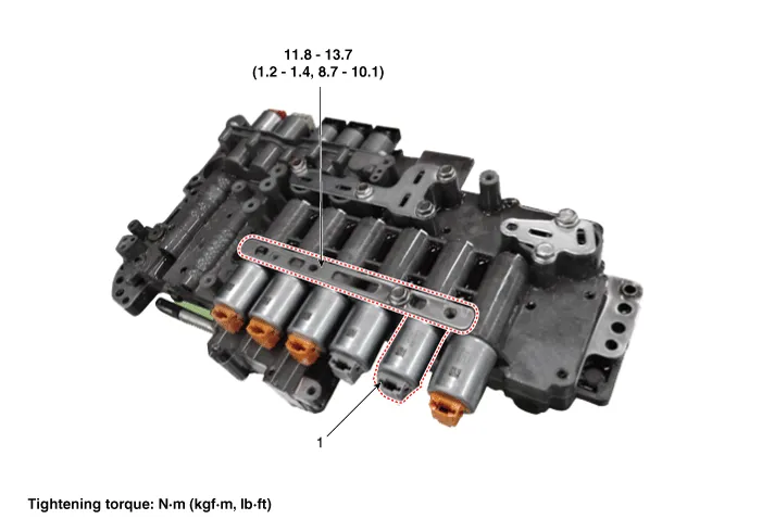
Remove the valve body assembly (A) after loosening the bolts.
|
| 6. |
Remove the E-module (A) after loosening the bolts.
|
| 7. |
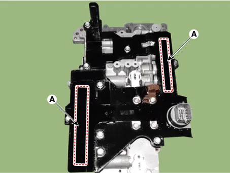
Remove the solenoid valve support bracket (A).
|
| 8. |
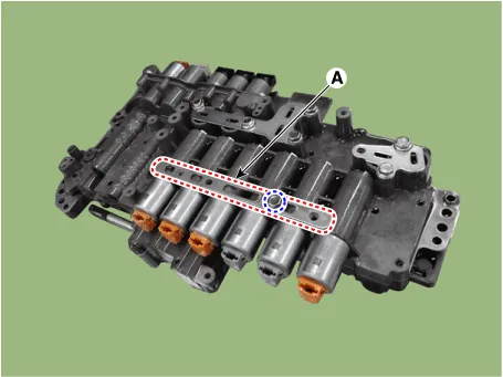
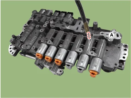
Remove the pin (A).
|
| 9. |
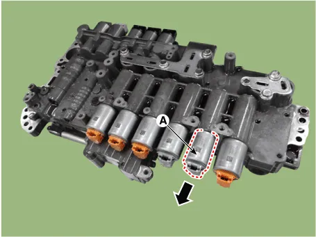
Remove the 4&OD clutch control solenoid valve (A).
|
| Installation |
| 1. |
Install in the reverse order of removal.
|
| 2. |
Perform the procedures below after installing.
|


Other information:
Kia Stinger (CK) 2018-2023 Service Manual: Rear Seat Belt Retractor
Components and components location Component Location 1. Rear seat belt retractor [LH] 2. Rear seat belt retractor [RH] Repair procedures Replacement When installing the belt, be careful not to damage the retractor.Kia Stinger (CK) 2018-2023 Service Manual: Steering Angle Sensor
Description and operation Description Steering Wheel Angle Sensor detects rotating direction of the vehicle.The rotating direction detected by the sensor is sent to the HECU as CAN signal via CAN communication. HECU detects speed of the steering wheel handling and the angle with this CAN signal. HECU also uses this signal as the input signal to control anti-roll.Categories
- Manuals Home
- Kia Stinger Owners Manual
- Kia Stinger Service Manual
- New on site
- Most important about car
