Kia Stinger CK: Fuel Delivery System / Low Pressure Fuel Pump
Repair procedures
| Inspection |
[Fuel sender]
| 1. |
Switch "OFF" the ignition and disconnect the negative (-) battery terminal. |
| 2. |
Remove the fuel pump assembly. |
| 3. |
Using an ohmmeter, measure the resistance between terminals 1 and 2 of sender connector (A) at each float level.
|


| 4. |
Also check that the resistance changes smoothly when the float moves from "E" to "F".
|
| Removal |
| 1. |
Release the residual pressure in fuel line. (Refer to the Fuel Delivery System - "Release Residual Pressure in Fuel Line") |
| 2. |
Switch "OFF" the ignition and disconnect the negative (-) battery terminal. |
| 3. |
Remove the rear seat cushion. (Refer to Body - "Rear Seat Assembly") |
| 4. |
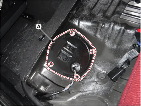
Remove the fuel pump service cover (A) after loosening the mounting screws.
|
| 5. |
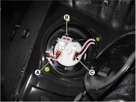
Disconnect the fuel feed quick-connector (A). |
| 6. |
Disconnect the fuel pressure sensor connector (B). |
| 7. |
Disconnect the fuel pump connector (C).
|
| 8. |
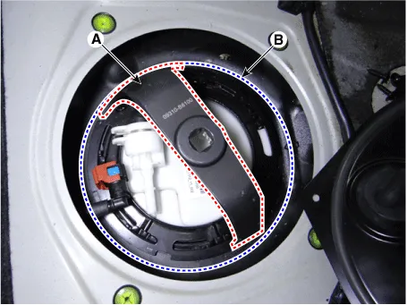
Remove the locking ring (A) by using the special service tool (B) [No.: 09310-B8100].
|
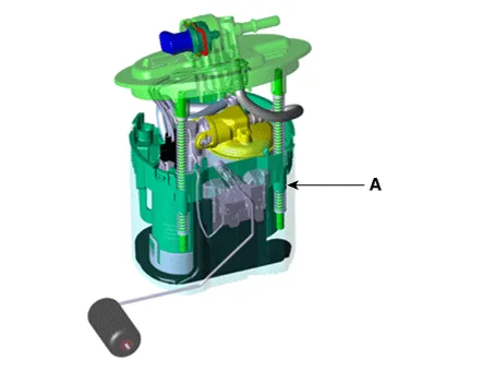
| 9. |
Remove the fuel pump (A).
|
| Installation |
| 1. |
Install in the reverse order of removal. |


Other information:
Kia Stinger (CK) 2018-2023 Service Manual: Purge Control Solenoid Valve (PCSV)
Specifications Specification Item Specification Coil Resistance (Ω) 18.5 - 22.5 [20°C(68°F)] Description and operation Description Installed on the surge tank, the Purge Control Solenoid Valve (PCSV) controls the passage between the canister and the intake manifold.Kia Stinger (CK) 2018-2023 Service Manual: AWD Control System
Components and components location Components Location 1. AWD ECU Description and operation Description The AWD ECU distributes the driving force to the front/rear wheel through controlling the multi plate clutch on the AWD transfer case by analyzing the input information, i.e. the wheel speed, accelerator and steering angle depending on the road condition and driving state.Categories
- Manuals Home
- Kia Stinger Owners Manual
- Kia Stinger Service Manual
- New on site
- Most important about car
