Kia Stinger CK: Automatic Transmission Control System / E-Shifter
Components and components location
| Components |

| 1. E-Shifter 2. Parking release actuator |
3. Parking release cable 4. Parking release lever |
Schematic diagrams
| Circuit Diagram |
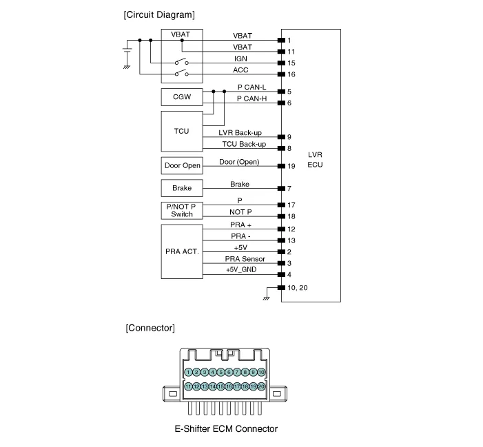
Description and operation
| Description |
| • |
Operating Principle: Any change in the lever position is detected and transmitted via electric signals from the electronic shift lever ECU to the TCM. |
| • |
Function |
| – |
Gear shifting signal transmission |
| – |
Shift lever display |
| – |
Shift locking |
| – |
System failure diagnosis |
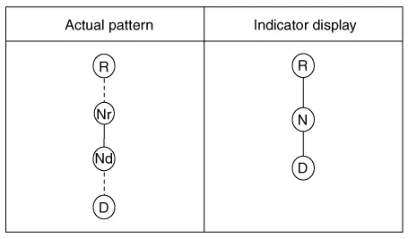
| • |
Electronic shift lever operation pattern
|
| • |
Operation order Flow diagram
|
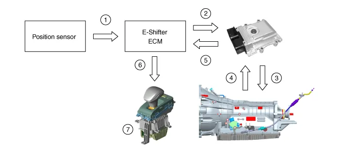
| 1) |
The lever position is detected and the data is sent to the electronic shift lever ECM. |
| 2) |
The lever position information is transmitted from the electronic shift lever ECM to the TCM (CAN + Hard wire). |
| 3) |
The TCM controls the AT so that the mode reflects the lever position. |
| 4) |
The TCM checks the information on the final shift mode of the AT. |
| 5) |
The TCM sends the information on the final shift mode to the electronic shift lever ECM. (CAN) |
| 6) |
The Electronic shift lever ECM sends the information on final shift mode to the indicator. |
| 7) |
Current information on the final shift mode appears on the indicator. |
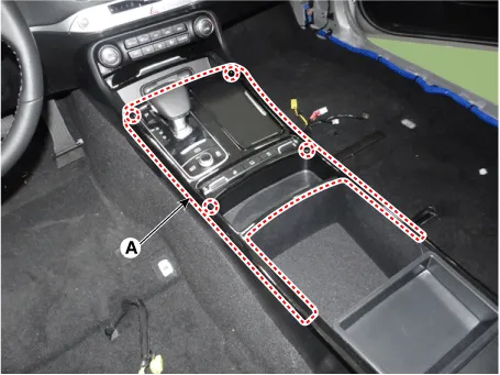
Repair procedures
| Removal |
| 1. |
Remove the upper console cover (A) using the remover.
|
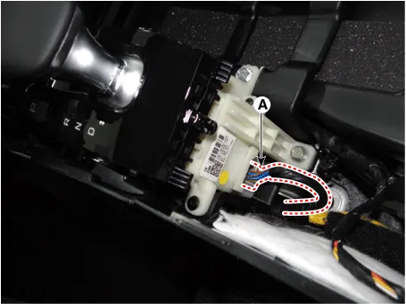
| 2. |
Disconnect the main connector (A).
|
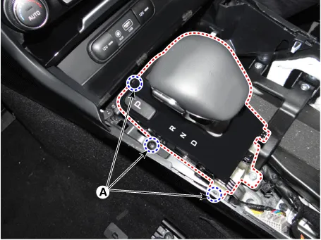
| 3. |
Loosen the E-shifter mounting screws (A).
|
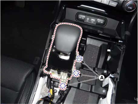
| 4. |
Loosen the E-shifter mounting bolts (A).
|
| Installation |
| 1. |
Install in the reverse order of removal. |


Other information:
Components and components location Component [THETA Engine] 1. Clutch Bolt 2. Limiter Bolt 3. Limiter & Hub Assembly 4. Snap Ring 5. Pulley 6. Compressor Assembly [LAMBDA Engine] 1. Clutch Bolt 2. Limiter Bolt 3. Limiter & Hub Assembly 4.Components and components location Components 1. Brake lamp switch 2. Brake pedal Description and operation Operation Operation principle of inductive non-contact switch 1. Use the high frequency magnetic field and the induced current that are generated by oscillation (to approved voltage) of coil in switch.Categories
- Manuals Home
- Kia Stinger Owners Manual
- Kia Stinger Service Manual
- New on site
- Most important about car
