Kia Stinger CK: Hydraulic System / Oil Cooler
Components and components location
| Components |

| 1. Oil cooler tube 2. Oil cooler pipe |
3. Oil cooler valve 4. Oil cooler |
Repair procedures
| Replacement |
Oil cooler
| 1. |
Remove the front bumper. (Refer to Body - "Front Bumper Aseembly") |
| 2. |
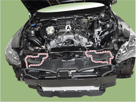
Remove the air intake shield (A).
|
| 3. |
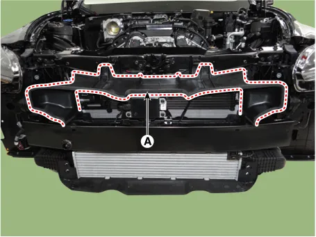
Remove the air guard (A) by loosening the bolts after separating the wiring fixing clip.
|
| 4. |
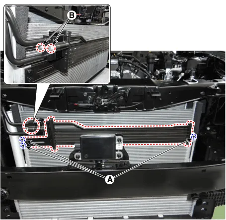
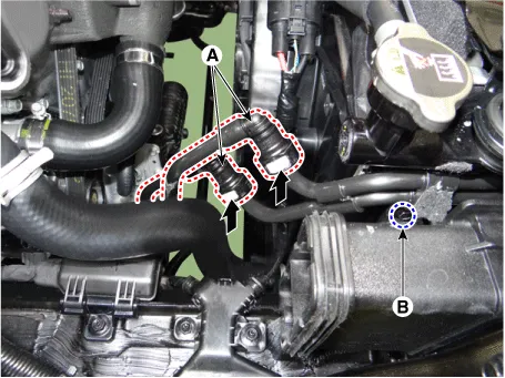
Remove the oil cooler after loosening the bolts (A, B)
|

| 5. |
Install in the reverse order of removal. |
| 6. |
Refill the automatic transmission with fluid. (Refer to Hydraulic System - "Fluid") |
Oil cooler valve
| 1. |
Remove the front bumper. (Refer to Body - "Front Bumper Aseembly") |
| 2. |
Remove the air intake shield (A).
|
| 3. |
Remove the air guard (A) by loosening the bolts after separating the wiring fixing clip.
|
| 4. |
Separat the oil cooler tube (A)and loosen the bolt (B).
|
| 5. |
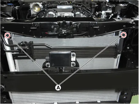
Remove the oil cooler valve (B) after loosening the bolts (A).
|
| 6. |
Install in the reverse order of removal. |
| 7. |
Refill the automatic transmission with fluid. (Refer to Hydraulic System - "Fluid") |
Oil cooler pipe
| 1. |
Remove the front bumper. (Refer to Body - "Front Bumper Aseembly") |
| 2. |
Remove the air intake shield (A).
|
| 3. |
Remove the air guard (A) by loosening the bolts after separating the wiring fixing clip.
|
| 4. |
Separat the oil cooler tube (A)and loosen the bolt (B).
|
| 5. |
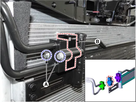
Loosen the condenser mounting bolt (A).
|
| 6. |
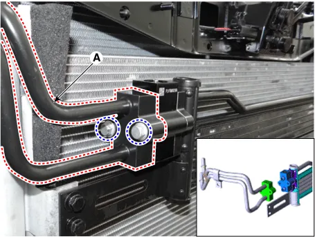
Remove the oil cooler pipe (A) after loosening the bolts.
|
| 7. |
Install in the reverse order of removal. |
| 8. |
Refill the automatic transmission with fluid. (Refer to Hydraulic System - "Fluid") |
Oil cooler tube
| 1. |
Remove the sub frame. (Refer to Suspension System - "Sub Frame") |
| 2. |
Removethe oil cooler tube (A).
|
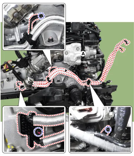
| 3. |
Install in the reverse order of removal. |
| 4. |
Refill the automatic transmission with fluid. (Refer to Hydraulic System - "Fluid") |


Other information:
Kia Stinger (CK) 2018-2023 Service Manual: Tail Gate Back Panel
Repair procedures Replacement • Use a plastic panel removal tool to remove interior trim pieces without marring the surface. • Take care not to bend or scratch the trim and panels. 1.Kia Stinger (CK) 2018-2023 Service Manual: Emission Control System
Components and components location Components Location 1. PCV Valve 2. Canister 3. Purge control solenoid valve (PCSV) 4. Fuel tank air filter 5. Catalytic converter (WCC) 6. Vapor hose (Canister ↔ Intake Manifold) 7. Vapor Hose (Canister ↔ Fuel Tank) 8. Ventilation Hose (Canister ↔ Atmosphere) 1.Categories
- Manuals Home
- Kia Stinger Owners Manual
- Kia Stinger Service Manual
- New on site
- Most important about car
