
Kia Stinger CK: Engine Control / Fuel System / Fuel Delivery System
Contents:
- Fuel Tank
- Low Pressure Fuel Pump
- Fuel Filter
- Fuel Pump Motor
- Sub Fuel Sender
- Fuel Sender Assembly
- Fuel Pump Control Module (FPCM)
- Fuel Pressure Sensor (FPS)
- Fuel Line
- Filler-Neck Assembly
- Delivery Pipe
- High Pressure Fuel Pump
Components and components location
| Components Location |
| Fuel Tank & Filler-Neck Assembly |
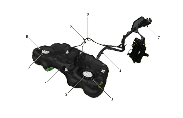
| 1. Fuel Tank 2. Low Pressure Fuel Pump 3. Sub Fuel Sender 4. Fuel Filler Hose |
5. Leveling Hose 6. Ventilation Hose 7. Filler-Neck Assembly 8. Fuel Pump Plate Cover |
| Low Pressure Fuel Pump |
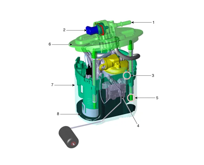
| 1. Fuel Feed Port 2. Fuel Pressure Sensor (FPS) 3. Fuel Filter 4. Fuel Sender |
5. Fuel Pressure Regulator
6. Head Assembly 7. Reservoir-Cup 8. Pre-filter |
| High Pressure Fuel Line |
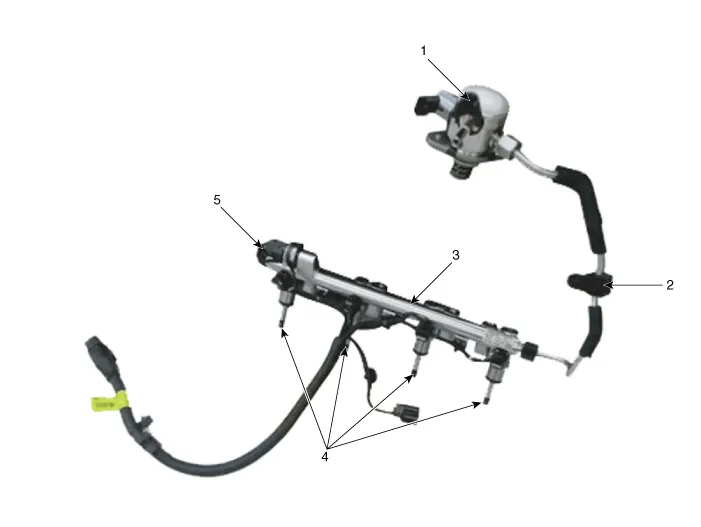
| 1. High Pressure Pump 2. High Pressure Pipe 3. Delivery Pipe |
4. Injector 5. Rail Pressure Sensor (RPS) |
Whenever the high pressure fuel pump, fuel pipe, delivery pipe, or injector is removed immediately after shutting off the engine, an injury may be caused by the release of highly pressurized fuel. Release the residual pressure in the high pressure fuel line by referring to the "Residual fuel pressure release procedure" below before removing any high pressure fuel system components. |

Fuel pressure test (low pressure system)
| Fuel Pressure Test (Low pressure system) |
| 1. |
Release the residual pressure in fuel line. (Refer to the Fuel Delivery System - Inspection - "Release Residual Pressure in Fuel Line".)
|

| 2. |
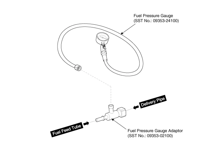
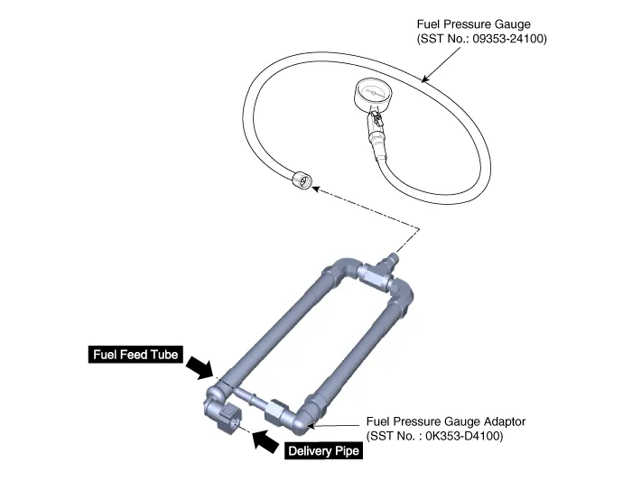
Install the Special Service Tool (SST).
|
| 3. |
Check for fuel leakage from connections on the low fuel feed tube, the low pressure inlet of high pressure fuel pump, and the SST components with ignition "ON". |
| 4. |
Measure the fuel pressure.
|

| 5. |
Release the residual pressure in fuel line. (Refer to the Fuel Delivery System - Repair Procedures - "Release Residual Pressure in Fuel Line").
|
| 6. |
Finish test.
|
Release residual pressure in fuel line
| Release Residual Pressure in Fuel Line |
Whenever the high pressure fuel fuse, fuel pipe, delivery pipe, or injector is removed immediately after shutting off the engine, an injury may be caused by the release of highly pressurized fuel. Release the residual pressure in the high pressure fuel line by referring to the "Residual fuel pressure release procedure" below before removing any high pressure fuel system components. |
Wear safety glasses and fuel resistant gloves. |
| 1. |
Switch "OFF" the ignition and disconnect the negative (-) battery terminal. |
| 2. |
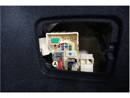
Remove the fuel pump relay (A).
|
| 3. |
Reconnect the negative (-) battery terminal. |
| 4. |
Run the engine for about 1 minute to lower the pressure in the low pressure line. |
| 5. |
Turn the engine off. |
| 6. |
Disconnect the low pressure fuel line quick connector at the High Pressure Pump. Use rags to cover opening and catch spills while removing the fuel line. |
| 7. |
Start the engine and let it idle until the engine stops. At this point the pressure should be under 30 psi. |
| 8. |
Proceed with the service or repair. Use rags to cover opening and catch spills when opening up the high pressure system. |
| 9. |
Reinstall / re-connect all components in reverse order of removal. Start engine and confirm proper operation, and make sure there are no fuel leaks. |
| 10. |
After completing, clear DTC(s) using KDS scan tool. (The procedure described above will cause DTC to set.) |
Fuel Tank ➤
Low Pressure Fuel Pump ➤
Fuel Filter
Repair procedures
| Removal |
Fuel filter cannot be replaced on its own; it should be replaced with the fuel pump assembly. (Refer to Fuel Delivery System - "Low Pressure Fuel Pump") |
| Installation |
Fuel filter cannot be replaced on its own; it should be replaced with the fuel pump assembly. (Refer to Fuel Delivery System - "Low Pressure Fuel Pump") |
Fuel Pump Motor ➤
Sub Fuel Sender ➤
Fuel Sender Assembly
Repair procedures
| Removal |
Main fuel sender cannot be replaced on its own; it should be replaced with the fuel pump assembly. (Refer to Fuel Delivery System - "Low Pressure Fuel Pump") |
| Installation |
Main fuel sender cannot be replaced on its own; it should be replaced with the fuel pump assembly. (Refer to Fuel Delivery System - "Low Pressure Fuel Pump") |
Fuel Pump Control Module (FPCM) ➤
Fuel Pressure Sensor (FPS) ➤
Fuel Line ➤
Filler-Neck Assembly ➤
Delivery Pipe ➤
High Pressure Fuel Pump ➤


Other information:
Kia Stinger (CK) 2018-2023 Service Manual: Electronic stability control (ESC)
The Electronic Stability control (ESC) system is designed to stabilize the vehicle during cornering maneuvers. ESC checks where you are steering and where the vehicle is actually going. ESC applies the brakes on individual wheels and intervenes with the engine management system to stabilize the vehicle. Electronic stability control (ESC) will not prevent accidents.Kia Stinger (CK) 2018-2023 Service Manual: Electric Waste Gate Actuator (EWGA)
Description and operation Desrcription Installed on the turbocharger, the Electric Waste Gate Actuator (EWGA) operates the vane in the Waste Gate Turbocharger (WGT) and regulates the compressed air amount based on the PWM signal from the ECM. This actuator consists of a DC motor which actuates the vane, a 2-step gear which increases torque of the DC motor, a position sensor which detects status of the vane, and an electric control unit which drives the DC motor.Categories
- Manuals Home
- Kia Stinger Owners Manual
- Kia Stinger Service Manual
- Fuel Tank
- Low Pressure Fuel Pump
- Fuel Filter
- Fuel Pump Motor
- Sub Fuel Sender
- Fuel Sender Assembly
- Fuel Pump Control Module (FPCM)
- Fuel Pressure Sensor (FPS)
- Fuel Line
- Filler-Neck Assembly
- Delivery Pipe
- High Pressure Fuel Pump
- New on site
- Most important about car
Contents
